I.INTRODUCTION
Condition monitoring (CM) of rotating machines receives much attention to ensure the high reliability, productivity, and safety of rotating machines. CM aims to use monitoring data collected from rotating machines to infer current machine health conditions, and subsequently, optimal maintenance activities can be scheduled to prevent unexpected accidents and consequences. Early machine fault detection and diagnosis could provide sufficient time for performing optimal maintenance actions and thereby prevent machine failures and severe accidents.
The commonly used technologies in CM include vibroacoustic measurements [1], oil analysis [2], process parameters [3], thermal imaging [4], and so on. Vibration-based CM becomes more and more popular in fault detection and diagnostics of rotating machines. The vibration responses measured externally are the manifestations of the internal dynamic forces, which can disclose the machine dynamics, for instance, manufacture errors, installation errors, load and speed oscillations, lubrication conditions, fluid–structure interactions, and machine faults. Vibration acceleration is widely adopted in practice because the accelerometers are cost-effective and have an extremely wide range of both amplitude and frequency. The primary types of vibration sensors are piezo-electric and piezoresistive accelerometers that are required to be firmly attached to the target surface. These commercial accelerometers dominate the vibration measurements of both academic and industrial research activities. Besides the contact types, there are non-contact near-field vibration transducers including eddy current transducers, capacitive transducers, self-inductance sensors, mutual inductance sensors, fiber-optic sensors, and so on. These sensors mainly obtain the displacement variation from a close distance with the targets. These near-field vibration transducers are susceptible to environmental factors, for example, temperature. The far-field displacement transducers are also popular in research and they are mainly optical probes, for instance, laser heads. These transducers usually require a special reflector on objects. Laser Doppler vibrometer (LDV) is a popular far-field vibration measurement instrument, providing accurate measurements of velocity in challenging applications. The principle is the proportional Doppler frequency shift to a surface that occurs when light is scattered by a moving surface and an exhaustive introduction of LDV systems is given in reference [5]. Both near and far field transducers are very and even extremely expensive for a single channel. The configuration of multiple channels in a test can raise the total costs to an unaffordable level. Scanning laser vibrometers alleviate the multiple channel problem to a certain degree. However, the scanning area of these devices is relatively small. The novel vibration sensing methods attract more and more attention owing to the benefits of vibration measurements. Farrar et al. [6] used a microwave interferometer to remotely measure the vibration of large structures. The extracted modal frequencies using microwave interferometer signals match very well with the conventional accelerometers, showing the accuracy of the non-contact microwave vibration measurement technique. Chen et al. [7] developed a video camera-based vibration measurement methodology for civil infrastructures.
Thanks to the fast development of micro-electro-mechanical systems (MEMS) technologies, the cost-effective MEMS accelerometers have been widely used in machine CM. The experimentation at the University Technology Centre of the University of Sheffield indicated the great potential of wireless sensors for structural health monitoring [8]. Baghli et al. [9] developed a wireless instantaneous torque meter using MEMS accelerometers and the experimental study verifies the accuracy of this wireless torque meter. Jiménez et al. [10,11] obtained the rotor orbit and rotating speed information using internal MEMS accelerometers and then an active control strategy leads to intelligent rotors with time-varying characteristics. Elnady et al. [12,13] installed a MEMS accelerometer on a shaft for investigating the critical speeds of rotating machines. The Centre for Efficiency and Performance Engineering continuously carries out research of the MEMS accelerometers in machine CM. Arebi et al. [14] monitored the misalignment fault of rotating shafts using a wireless MEMS accelerometer, which shows a better detection result than the instantaneous angular speed (IAS) measurements from an optical encoder. To eliminate the negative influence of the gravity acceleration, Feng et al. [15] employed the Hilbert transform-based analytic signal method to reconstruct the tangential acceleration from two orthogonal axis vibration signals in a single triaxial MEMS accelerometer. The obtained torsional vibration shows promising health monitoring of reciprocating compressors. The comparison study of two gravity cancellation methods was carried out by Mones et al. [16], and the analytic signal method has higher accuracy. These aforementioned applications focus on the tangential acceleration from the MEMS accelerometers, aiming to get the torsional vibration in a low frequency range.
Although vibration measurements are informative, they suffer from the disadvantage of strong background noise and complicated modulations. The reduction of the background noise and interferences and the incrementation of signal to noise ratio (SNR) are always challenging tasks in machine CM. In most circumstances, the extraction of useful information relies on the advanced and complicated signal processing approaches, for example, filtering [17–19], wavelet transform [20–22], higher order spectral analysis [23–25], time synchronous averaging [26–28], correlation analysis [29–31], and stochastic resonance [32–34]. These advanced methods produce good detection and diagnostics. However, the complexity of these algorithms requires intensive computing and often suffers from issues of less robustness and low reliability. Other than developing advanced signal processing methods, another more effective research direction is to increase signal quality by introducing emerging sensing technologies. Thanks to the cost-effective, compact, and high-performance MEMS accelerometers, the on-rotor sensing (ORS) technology was developed to overcome the intricate and time-varying transmission paths and poor SNR of the conventional vibration signals by considering the working principles of rotating machines.
II.AN ORS SYSTEM
Vibration signals acquired from a running machine using on-casing accelerometers are always subjected to various background noise and complex signal transmission paths, which significantly weaken machine fault signatures. To minimise these influencing factors and extract desired signals for early fault detection and accurate diagnosis, a promising approach is to develop advanced sensing methods for high SNR signals. Consequently, the ORS system was developed with regard to the working principle of rotating machines. The rotor is the core component of a rotating machine and the dynamic responses of the rotor give valuable information about machine health conditions. When a localized fault occurs on rotating components, for example, bearings or gears, an impulse vibration is generated due to either the rotor or the stator passing through it and consequently, the successive impulsive responses become the significant indicator of rotating machine faults [35]. Other than monitoring the dynamic responses of stationary components, the ORS directly captures dynamic rotor responses by installing single or multiple triaxial accelerometers on the rotor. The rotor and casing are usually separated by rolling or journal bearings, and the undesired vibration is attenuated significantly during the transmission from casing to the rotor. Therefore, the rotor responses are less contaminated by the ambient vibration. Furthermore, the relative position between ORS sensors and rotors is fixed, and the ORS signals are exclusive of the complicated transmission path.
A.THE HARDWARE OF AN ORS SYSTEM
As shown in Fig. 1, an ORS hardware system consists of four main modules: a sensing unit, a processing unit, a wireless communication unit, and a power unit. The sensing unit can be any transducers that are useful for machine CM, for example, vibration, acoustics, gyroscope, magnets, strain, temperature, pressure, humidity, and so on. The data sets from these transducers are informative to assess the health conditions of the target machine as well as the working environment. The signals from sensors can be acquired by the processing unit and then transferred wirelessly via the communication unit. The end-user device can be used to receive and analyze the various measurements online. Furthermore, these measurements can be uploaded to the cloud for intelligent monitoring on a large scale. Then, cloud computing can serve large quantities of clients from design, manufacture, service, and maintenance. In addition, the compact ORS hardware system consumes quite limited power, and it can achieve maintenance-free if combined with the energy harvesting technique [36,37]. The computing capacity of the unit keeps increasing with the development of advanced MEMS technologies.
As vibration-based CM is popular and effective, the vibration-based ORS is the main research content in this paper. The vibration sensor integrated into the ORS system is a triaxial MEMS accelerometer. The inherent orthogonality between axes leads to unique benefits in characterizing ORS vibrations.
B.ORTHOGONAL ORS VIBRATIONS FOR FAULT DIAGNOSTICS
ORS accelerometers can produce signals to reflect various rotor responses including rotational IAS and transverse vibration when an ORS accelerometer is installed on a horizontal rotor as shown in Fig. 2. For this more generic scenario, the ORS accelerometer is installed eccentrically with the radius of which can be controlled according to the requirement and operating conditions. In most circumstances, the radius will be the radius of the exposed shaft. Another common scenario is that ORS can be installed at the shaft end, where can be as small as possible. The ORS sensor can be installed on the exposed shaft or shaft ends with power adhesives or suitable holders. The installation method of the ORS sensor is non-invasive and non-intrusive. As shown in Fig. 2, the triaxial accelerometer in the ORS system has three orthogonal outputs in nature. Considering axis of the ORS accelerometer is aligned with the axial direction of the shaft, the and axes will pick up both the radial and torsional vibration signals. In Feng et al. [15], the torsional response has been comprehensively investigated. To make full use of the ORS measurement, this study will focus more on the examination of radial responses.
 Fig. 1. Schematic diagram of an ORS system.
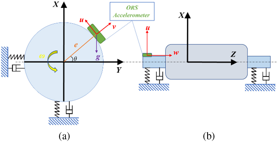 Fig. 2. Installation schematic diagram of an ORS accelerometer.
The X-Y coordinate is global and fixed, while the - coordinate is local and will rotate with the ORS sensor. According to the geometric relationship, responses in the direction of and can be expressed as
where and are the vertical and horizontal vibrations, respectively. is the rotation angle of the rotor and equals to . The centrifugal acceleration is a constant at steady rotating speeds and hence it can be omitted in dynamic analysis, which can also be very small when ORS is at the end of the shaft. Assuming that and from rotating machines are periodic signals, they can be represented by the Fourier series.where and are the fundamental frequency of the vertical and horizontal rotor vibrations, which may be the same as the rotating frequency. However, the relationship between these three frequencies is not discussed in this paper. The following deduction is carried out on the assumption that vertical and horizontal vibrations are periodic. Consequently, the dynamic vibration responses from the ORS sensor can be expressed as follows:All the components from and have a phase shift of , and is the Hilbert transform of the inherently. Following the linearity property of the Hilbert transform, the ORS vibrations of and can constitute an analytic signal:
where is the imaginary unit. The analytic signal is significantly useful in machine CM. It can be used to calculate the instantaneous amplitude (also named as envelope) and instantaneous frequency. Both the amplitude and phase provide rich and accurate information for detection diagnosis. Moreover, this analytic signal is obtained from the time domain directly, which overcomes the inevitable end effect problems of Hilbert transform-based analytic signals which are often calculated through a frequency domain algorithm.III.CASE STUDIES
A.ORS-BASED BEARING FAULT DIAGNOSIS
1)TESTS OF BEARING FAULT
Bearing defects are the most prevalent failure type in induction motors, which accounts for about 40% of common motor faults [38]. To demonstrate the effectiveness of ORS vibrations, the motor bearing fault tests were conducted firstly. Fig. 3(a) shows the schematic diagram of the induction motor test rig, which consists of an induction motor as the power source, a DC generator as the torque resistance, and a flexible coupling as the power line connection. The speeds and loads of the whole rig are controlled by the advanced control system. In the meantime, a conventional integrated electronics piezo-electric (IEPE) accelerometer was attached to the motor shell near the faulty bearing. To monitor the rotating speed, a commercial optical encoder was connected to the motor rotor from the fan end. The key specifications of the test apparatus are listed in Table I. A photograph of the whole rig was given in Fig. 3(b). The ORS device was placed at the drive end with the flexible jaw couplings. By glueing the accelerometer element to the shaft end, it allows the vibrations of the motor rotor to be captured directly. The detailed specifications of the ORS system and the data collection smartphone app is shown in Fig. 3(c). The frequency range of 3,200 Hz can cover the first a few vibration modes of the motor rotor including more than 20 harmonics of the bearing characteristic frequencies. The microprocessor can have sufficient capacity for edge computing. In this instance, it is mainly used to control data flow for continuously transferring raw data to a smartphone via its BLE module. In this paper, the ORS system is configured to collect the data completely and then transmit it to the smartphone. To ensure the completeness of the raw data, real-time data streaming is not used in this paper. With the increase of transmission bandwidth, for example, Bluetooth 5 and Wi-Fi, real-time data streaming can be achieved. The data are then analyzed in Matlab and compared with that of on-casing data sets. Fig. 3(d) depicts the outer race fault of the bearing. Obviously, the defect location is closer to the on-casing accelerometer. In this case study, the motor was operated at 60% and 70% of the full motor speed.
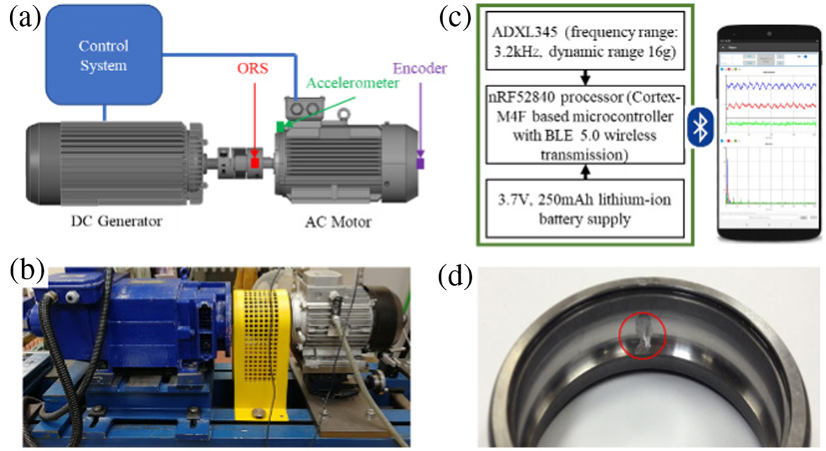 Fig. 3. (a) The schematic diagram of the test rig; (b) the photograph of the test rig; (c) the ORS and app; and (d) the photograph of the bearing fault.
Table I. Key Specifications of the test rig equipment
| Equipment | Model | Key specification |
|---|---|---|
| Variable frequency drive | 650V4 | 15 kW, 3 kHz |
| Induction motor | 112MA/4 | 1420 rpm, 4 kW |
| DC generator | CBH5025 | 1500 rpm, 4 kW |
| Data acquisition device | YE6232B | 16 channels, 96 kHz |
| On-casing accelerometer | CA-YD-185 | 5·0 mv/(m/s2), 0·5–5000 Hz |
| Encoder | RI32-O/100 ER.11 KB | 100 ppr, 6000 rpm |
2)ORTHOGONAL ORS VIBRATIONS-BASED BEARING DIAGNOSIS
Figure 4 shows the temporal waveforms of the ORS and on-casing vibrations when the motor ran at 60% speed. In Fig. 4(a) and (b), the waveforms depict the rotor vibrations at radial and tangential directions. The dominant component is the oscillation of the gravity acceleration, of which the frequency is the rotating speed and this component can be used for accurate speed estimation. The axial direction vibration in Fig. 4(c) has a smaller amplitude because it represents the axial movement of the rotor which is usually small in rotating machines. The on-casing vibration captured by the conventional accelerometer is displayed in Fig. 4(d). The on-casing vibrations are rich in various components due to structural vibration interferences. The conventional accelerometer is exclusive to the influence of gravity and the low frequency does not show a dominating component.
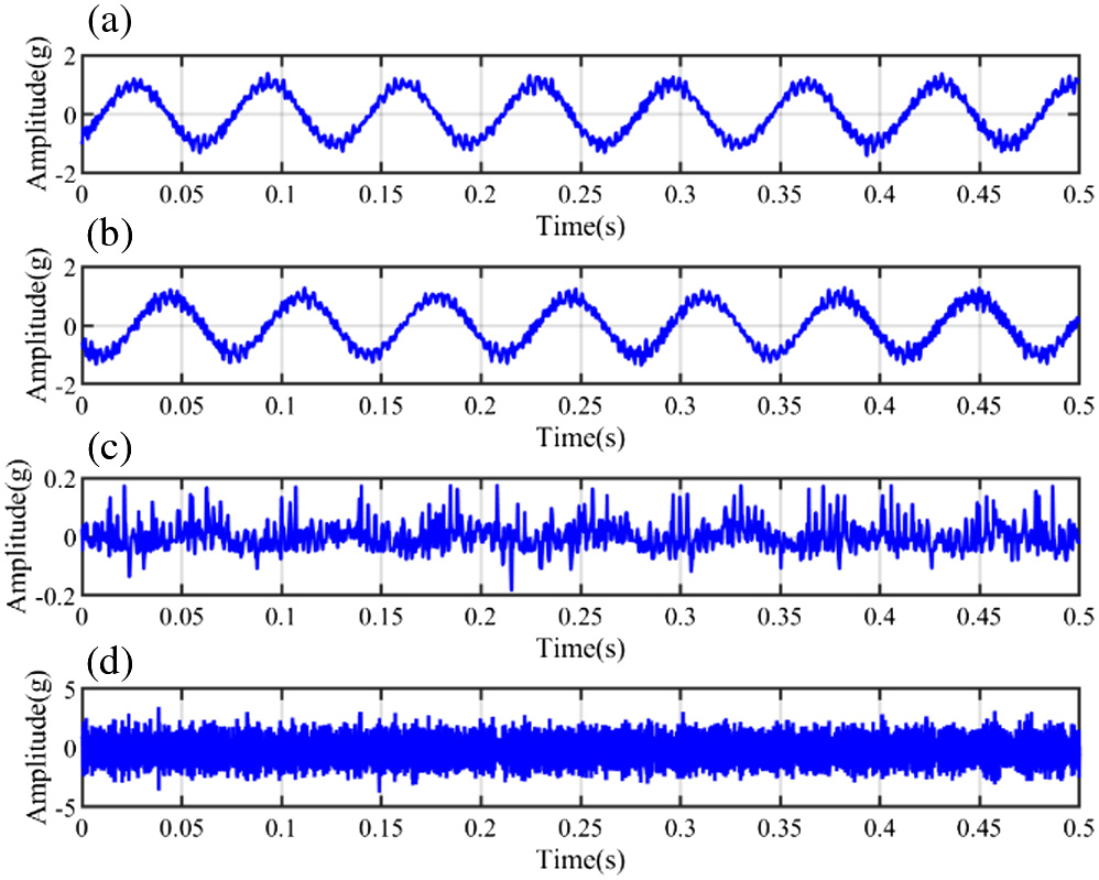 Fig. 4. Waveforms of: (a) ORS vibration u; (b) ORS vibration v; (c) ORS vibration w; and (d) on-casing vibration.
The amplitude spectra by fast Fourier transform (FFT) are given in Fig. 5. From Fig. 5(a) and (b), it can be seen that the spectra of and vibrations from ORS are quite similar because of the fixed relationship between the ORS accelerometer and the motor rotor. The high amplitude frequency at around 625 Hz is the natural frequency of the bending mode of the motor rotor.
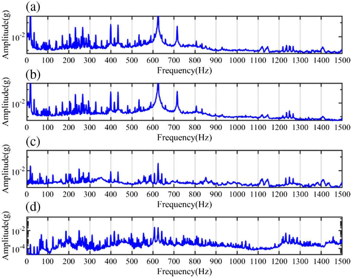 Fig. 5. Amplitude spectra of: (a) ORS vibration u; (b) ORS vibration v; (c) ORS vibration w; and (d) on-casing vibration.
The axial vibration spectrum in Fig. 5(c) has a reasonably low amplitude as the induction motor has little axial excitations, but mainly rotational and translational excitations due to mechanical eccentricity, electric asymmetricity, and residual unbalanced supplies. Fig. 5(d) shows that the amplitude of the on-casing vibration spectrum in the same frequency band is also very low, which is mainly due to the low transmissibility of the casing structure.
The envelope analysis is the most popular demodulation method for bearing fault detection and diagnosis. It is widely known that an optimal frequency band leads to the best diagnostic results of the bearing faults. The determination of optimum frequency bands is always a difficult task in demodulation analysis. Instead of using intricate algorithms, the informative frequency band can be easily identified according to the rich discrete components in the amplitude spectrum. Thereafter the frequency band from 100 Hz to 500 Hz was selected to demodulate the bearing fault signatures, and the reason to select this frequency band is that it is rich of sparse components and shows strong modulation features. To minimize the interference of other components, the bandpass filter is used to obtain the narrow band ORS signals that then construct analytic signals. Then the envelope of ORS vibrations is obtained by the absolute values of the analytic signal according to Equation (4), and the envelope of the on-casing vibration is obtained using conventional Hilbert transform. Figure 6 depicts the envelope spectrum of the ORS and on-casing vibrations at 60% speed. It is obvious that the amplitude of the fault characteristic frequency of the ORS vibrations is much greater than that of the on-casing vibrations, indicating that on-casing vibrations probably are less sensitive to incipient bearing faults. Especially, the seeded fault locates on the outer race and the on-casing accelerometer takes better chances to have higher SNR fault signatures. Therefore, it is demonstrated that ORS orthogonal measurements show more convincing diagnostic results. It is worthy of mentioning that the employed ORS accelerometer only has a data accuracy of 13 bits, which is much less accurate than that of a powerful 24-bit data acquisition instrument used for the on-casing vibration sensor.
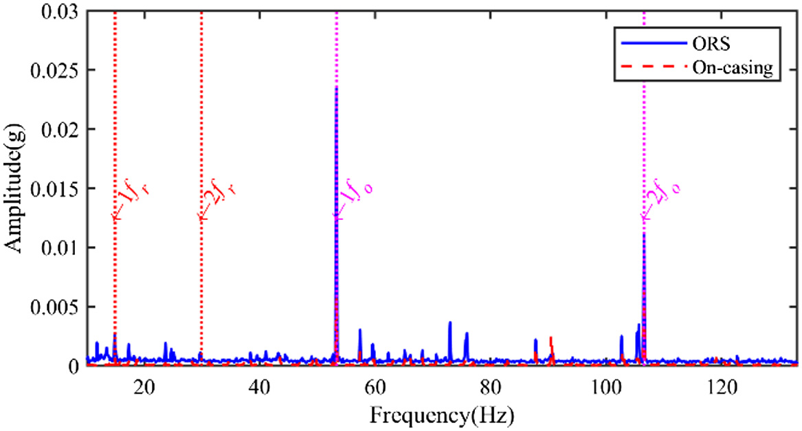 Fig. 6. Envelope spectra of ORS and on-casing vibrations at 60% speed.
Figure 7 shows the envelope spectrum of the filtered signals in the frequency band from 100 Hz to 500 Hz at 70% speed. In addition to frequency components at , it also shows cage modulation effect. This indicates the imperfection of the cage which becomes more significant when the speed is higher. It is obvious that the amplitude of the fault characteristic frequency of the ORS signal is much higher than that of the on-casing vibration signal, which demonstrates that the ORS signal can achieve more reliable diagnostics.
 Fig. 7. Envelope spectra of ORS and on-casing vibrations at 70% speed.
B)ORS-BASED MOTOR FAULT DIAGNOSIS
1)TESTS OF A HALF-BROKEN ROTOR BAR (BRB) ROTOR
BRB is another common fault in induction motors due to stress concentration and manufacturing errors. This BRB fault test was conducted using the same test rig as the bearing fault tests in Fig. 3. The instrumentation including the ORS sensor, the IEPE accelerometers, and the encoder is kept the same configuration in Table I. The half BRB fault is simulated by drilling a shallow hole on one bar of the rotor in Fig. 8. The motor was operated at 80% of the full speed under 20%, 50%, and 80% of the full load.

2)COMPARISON OF THE ORS AND CONVENTIONAL VIBRATIONS
It is well known that the motor BRB fault generates sidebands around the rotating frequency due to the additional torque oscillation-induced frequency modulation phenomenon [39]. The amplitude spectra of the ORS vibrations and on-casing vibrations are shown in Fig. 9. In Fig. 9(a), the characteristic fault sidebands around the rotating frequency are obvious even in a light load working condition. In contrast, the on-casing vibration measurements in Fig. 9(b) show little amplitude at the expected sidebands and are unable to detect the half BRB faults for sure.
 Fig. 9. Amplitude spectra of vibrations at 20% load: (a) the ORS u vibration; (b) the on-casing vibration.
As the analytic signal construction method is highlighted in the paper, the instantaneous phase can be estimated using the analytic signal if the input is a monocomponent signal. Therefore, the instantaneous phase signal is estimated from the filtered orthogonal ORS outputs around the rotating frequency. The frequency bandwidth is three times the BRB fault frequency, and the reason for a narrow frequency band is to get a monocomponent signal. The same frequency band was applied to the on-casing vibration signals, and the instantaneous phase is estimated by the conventional Hilbert transform-based analytic signal. The spectra of the obtained instantaneous phase are displayed in Fig. 10. It can be seen from Fig. 10(a) that the half BRB fault can be diagnosed effectively by the ORS signals, while the on-casing vibrations in Fig. 10(b) are unable to resolve the BRB fault.
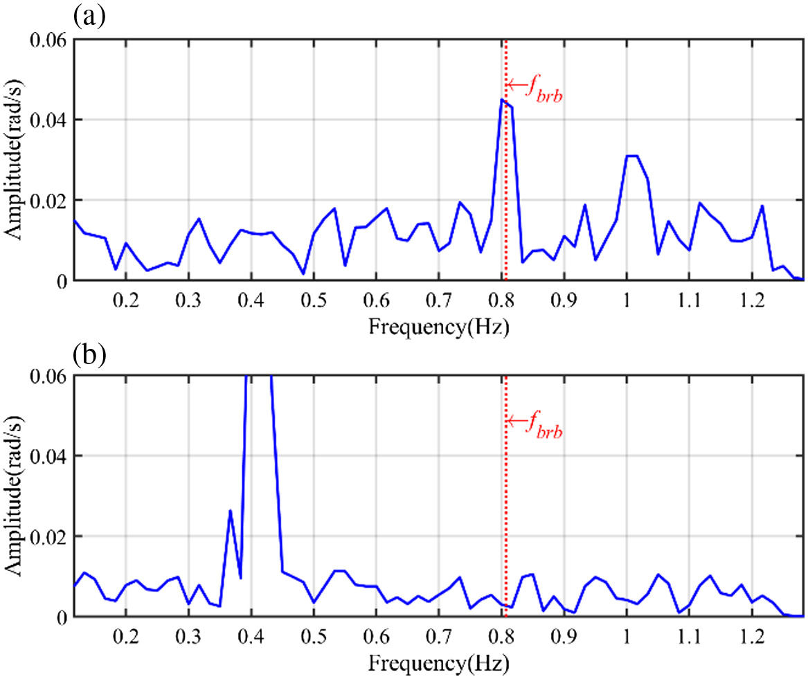 Fig. 10. Spectra of the instantaneous phase at 20% load: (a) ORS vibrations; (b) on-casing vibrations.
Moreover, with the increase of the loads, the BRB fault signatures become more and more pronounced and the BRB faults can be easily detected in the high load working conditions. The spectra of the instantaneous phase under the 50% and 80% loads are shown in Figs. 11 and 12, respectively. Both ORS and on-casing vibration signals can detect the half BRB faults in the medium and high load conditions. In summary, the successful diagnosis of the small rotor fault demonstrates the accuracy and reliability of ORS vibration measurements.
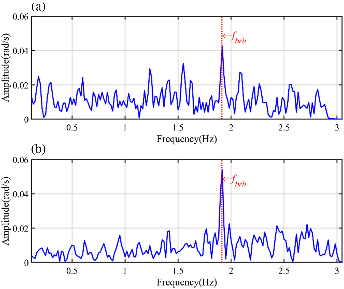 Fig. 11. Spectra of the instantaneous phase at 50% load: (a) ORS vibrations; (b) on-casing vibrations.
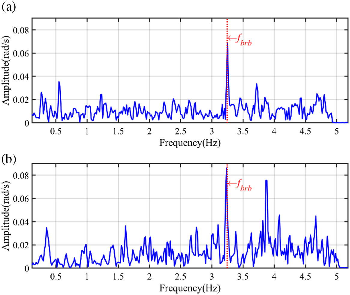 Fig. 12. Spectra of the instantaneous phase at 80% load: (a) ORS vibrations; (b) on-casing vibrations.
IV.CONCLUSIONS
In this paper, the ORS technology is proposed as a novel and effective method in CM of rotating machines. The orthogonal outputs of the ORS bring an efficient analytic signal construction approach, making it more convenient to use amplitude and phases information for detection and diagnostics. Especially, these can be achieved by FFT, which is more efficient and reliable compared with using complicated signal processing tools. This unique advantage of the ORS vibrations has been benchmarked with a high-performance on-casing IEPE accelerometer. It shows the ORS signals are more effective in detecting incipient rotor faults including bearing defects and BRBs. With the development of advanced MEMS and nanotechnology, the ORS technology will become more powerful in frequency bandwidth and data accuracy for machine CM, paving a framework for developing a sparsity sensing and smart rotor system.