I.INTRODUCTION
Planetary gearboxes are widely used in a number of applications, such as wind turbine and helicopter transmissions, but their complexity poses a challenge for the condition monitoring community. One aspect of this complexity involves the movement of all the mesh points, which gives rise to modulation of the gear mesh signal from the varying transmission path to the (usually fixed) measurement point. This modulation creates sidebands around the gearmesh frequency in the vibration spectrum, and the distribution of these sidebands has been widely studied [1–5]. At the same time, it is well established that non-uniform gear faults create a modulation of the vibration signal around the gearmesh frequency [6,7], so a thorough understanding of sideband distribution is very important for gear diagnostics.
This paper investigates the effect of one source of modulation in planetary gearboxes: the phase modulation of the measured vibration signal arising from the time-varying propagation delay between the vibration source and the measurement point, assumed to be fixed on the ring gear. Existing studies have assumed this modulation effect to be negligibly small, and the present paper intends to test that hypothesis. This is done by quantifying the contribution of the propagation delay to the sideband structure in the amplitude spectrum and establishing the boundary conditions under which the contribution needs to be considered. It is hoped this will lead to an improved understanding of forced vibrations in planetary gearboxes and increase the confidence with which existing diagnostic techniques can be applied. Following is a short review of papers considered to be the most relevant to the present study.
McFadden and Smith [1] proposed a model that explained the asymmetric sidebands around the tooth mesh frequency in epicyclic gears. The model assumes a fixed transducer on the ring gear and a uniform gear mesh vibration for an observer rotating with the planet carrier. The use of a response function between gearmesh and transducer results in an amplitude modulation of the gearmesh vibration measured from each planet by the fixed transducer. The observed overall vibration is the sum of the amplitude modulated gearmesh vibrations of each planet taking into account their angular position and mesh phasing [8]. According to their explanation, the symmetric sidebands produced by each single planet result in asymmetric sidebands in instances where the planets have out-of-phase meshing [3,8]. This can be understood with respect to a stationary transducer perceiving one dominant planet gear after another, each with a phase-offset gearmesh component relative to the previous planet, such that the measured response includes N distinct phase transitions of the gearmesh component each planet carrier cycle (N = number of planets) [9]. Mesh phasing has been exploited recently as a diagnostic tool to enable improved detection and location of faulty planet gears [10,11].
Perhaps the most detailed study of the sidebands of planetary gears was done by Inalpolat and Kahraman [3]. They used a model to investigate the dependencies of frequency and amplitude of the sidebands around the gear mesh frequency. Key parameters such as number of planets, planet position angles, planet phasing and number of teeth were used to categorise planetary gearboxes into five groups, with each group representing a different sideband structure in the amplitude spectrum. In their vibration model, Inalpolat and Kahraman used amplitude modulation to describe the influence on the measured vibration signal of the varying transmission path from the planet-ring tooth mesh to the measurement point fixed on the ring gear. They described this modulation using a Hanning window of length equal to the planet pass period. Hence the modulation function of each individual planet depends on the number of planets and actually falls to zero at the mid-point between planets (despite this having little physical justification, since the modulation function should be independent of the number of planets). An experimental gear setup was used to validate the model, and it showed that the experimental results matched the sideband predictions of each group.
Molina Vicuña [12] contributed with analysis of vibration and acoustic emission signals of epicyclic gears. In the vibration analysis a model was introduced that explains the spectral structure of vibrations generated by non-faulty planetary gearboxes, and the focus was on the condition monitoring of the gears by assuming a fixed accelerometer on the ring gear. As in [3], Molina Vicuña sought to link the vibration characteristics to the gearbox parameters with a focus on the amplitude modulation of the gear mesh vibration depending on number of planets, planet positions, planet phasing and number of teeth. Using these parameters, Molina Vicuña divided the gearbox into four groups and argued that the group definition of [3] can be generalised by stating “the phase angle of the gear meshes is evenly distributed in the range [0, )”. For each group Molina Vicuña described the spectral structure and gave examples using the mentioned gearbox parameters. It was explained that the spectral structure is characterised by the phase difference between the gear meshing of each planet, the amplitude modulation due to the transmission path variation and the phase difference of the transmission paths of each gear meshing. Molina Vicuña also described the transmission of vibrations by four transfer paths: two of which related to the vibration generated in the planet-ring gear meshing: (i) through the ring gear to the transducer (with the modulation function spanning the carrier rotational period, a more physically justifiable proposal than the planet pass period used in [3]), and (ii) through the sun gear and via the sun gear shaft bearing to the transducer on the ring gear. The latter transmission path produces another potential carrier-speed modulation effect as the frequency response function would change with the direction of force applied to the sun gear shaft, this being an altogether separate phenomenon from any ring gear modulation effect, where both direction and position of applied force change at carrier speed. However, empirical results suggest that modulation due to changing angle of applied force on the sun is small, and it is usually assumed that the ring gear effect dominates the resultant modulation pattern. Molina Vicuña [12] confirmed this by explaining that only the magnitude of the gear mesh frequency and its harmonics, but not the magnitude of the sidebands, is influenced by the sun gear transmission path effect, and his model showed good agreement with measurements on industrial and test bench planetary gearboxes.
Liu et al. [13] used the lumped parameter model developed in [14] to investigate planetary gearbox transmission paths. They considered two main transfer paths: inside the gearbox and along the casing, and found that “vibration amplitude is a function of the relative length of the transmission path”. Further examples of similar studies into planetary transmission path effects are given in [15,16].
While the above-mentioned papers point out the necessity of understanding transfer path effects on planetary gearboxes, to the authors’ knowledge no publications have analysed or quantified the periodic signal propagation delay of the vibration signal caused by the time varying transmission path between vibration source and sink. Molina Vicuña [12] pointed out that for his model the time delays of the vibrations generated in the planet-ring gear meshes and of the vibrations generated in the sun-planet gear meshes were assumed negligible, but no proof was given. McFadden and Smith [1] assumed that the time delay caused by the propagation of the vibration around the annulus is small. Meanwhile, Inalpolat and Kahraman stated that a more detailed investigation is needed to model the “transfer path between a given gear mesh and the point of measurement accurately” [3]. Liu et al. stated that “phase differences induced by the different lengths of transmission paths are not considered because of the short length difference between transmission paths and the high transmission velocity of vibration signals” [13].
With respect to parallel gears, McFadden described in [17] that the gearmesh vibration needs to pass through the gears, shafts, bearings, and case before reaching the transducer, and so the measured signal will inevitably be shaped by this transfer function. The influence of the transfer path on the vibration signal and especially the resulting phase modulation was researched by Stander and Heyns [18,19] for variable speed applications. The quantification of phase distortion, as well as amplitude distortion, and its influence on order tracking and subsequent analysis was pointed out by Borghesani et al. [20]. Randall et al. used cepstral liftering to remove the amplitude distortion from transfer function effects for gear diagnostics under variable speed, but the method is unable to cope with phase changes from the transfer function [21,22].
The authors propose here that for planetary gearboxes, the signal propagation delay can be modelled as a periodic phase modulation of the gearmesh vibration signal. Yet this phase modulation needs to be distinguished from the phase shift described in [18–22], which is caused by the structural response of the system. The phase shift under investigation is caused purely by the signal propagation delay, and the propagation velocity is assumed to be constant over the whole frequency range of the signal. This paper will therefore complement the findings of Borghesani et al. [20] by delivering further insights about the transfer path between vibration source and sink.
In Section II, an experiment for determining the signal propagation delay is described, and the results used in Section III to develop a linear vibration model of the propagation delay. The effect of the delay on the vibration analysis of industrial gearboxes is then discussed in Section IV, and conclusions given in Section V.
II.MEASUREMENTS OF SIGNAL PROPAGATION DELAY ON A RING GEAR
Signal propagation delay is described as the period of time a signal needs to travel a defined distance. The main vibration signal source in gearboxes is the so-called meshing (or transmission) error, which arises from deviations from the ideal involute tooth profile [23]. These deviations have a number of potential causes, the most pronounced of which is usually the variation in meshing stiffness caused both by variations in the number of tooth pairs in mesh at any given time, and by movement of the contact point along the gear flanks. Hence, through this varying stiffness a parametric excitation is created, introducing periodic vibration at the gearmesh frequency.
In a planetary gearbox, gear mesh vibration is caused by the planet-ring gear meshing and the sun-planet meshing. The vibration is then propagated through the different components of the gearbox. The path between the source and the sink is the transfer path. The sink is the vibration transducer and is considered here to be mounted on the ring gear perimeter. To allow a more straightforward investigation of the phase shift effect, this paper limits the investigation to the planet-ring gear meshing and the propagation of the signal through the ring gear to the transducer.
To estimate the delay of the vibration that propagates through the ring gear, impact testing was conducted on a free-floating ring gear with a diameter of approximately 2040 mm, and vibration response signals were recorded. The test was conducted using an impact hammer, which applied a force on the tooth at the pitch circle and in the direction normal to the tooth surface (∼20° from the tangential). The ring gear was set up with radially mounted accelerometers spaced at 45° intervals around half the perimeter, as shown in Fig. 1. Therefore, the distance along the perimeter between the transducer at 0° and 180° was 3204 mm. All transducers were sampled at 51.2 kHz and synchronised. An impact hammer was used to excite the ring gear tooth closest to the transducer mounted at 0°, as shown in Fig. 1.
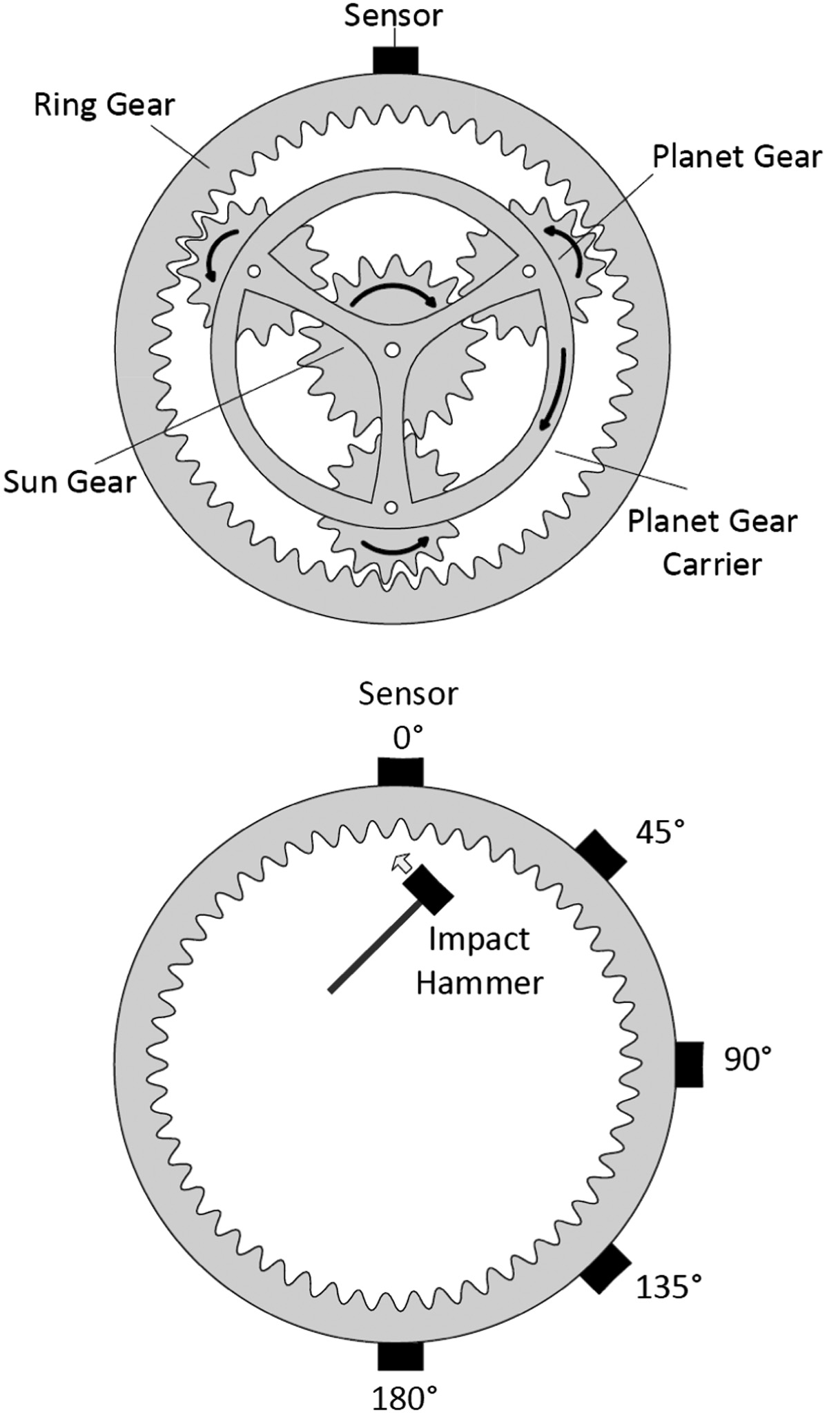 Fig. 1. Planetary gear overview and signal propagation delay experiment.
Figure 2 shows this phase difference in the responses from the 0°, 90° and 180° points to one excitation. The propagation delay is measured using a threshold of 0.01 g of the absolute value of the measured acceleration, whereupon the signal is assumed to have reached the measurement point at the instant the threshold is exceeded. The propagation delay for each response point is then calculated as the difference between this instant and that determined for the 0° position. For the example given in Fig. 2, the delays extracted are and , and the distances on the perimeter are and . Two other sensor positions at 45° and 135° were included and the experiment was repeated ten times.
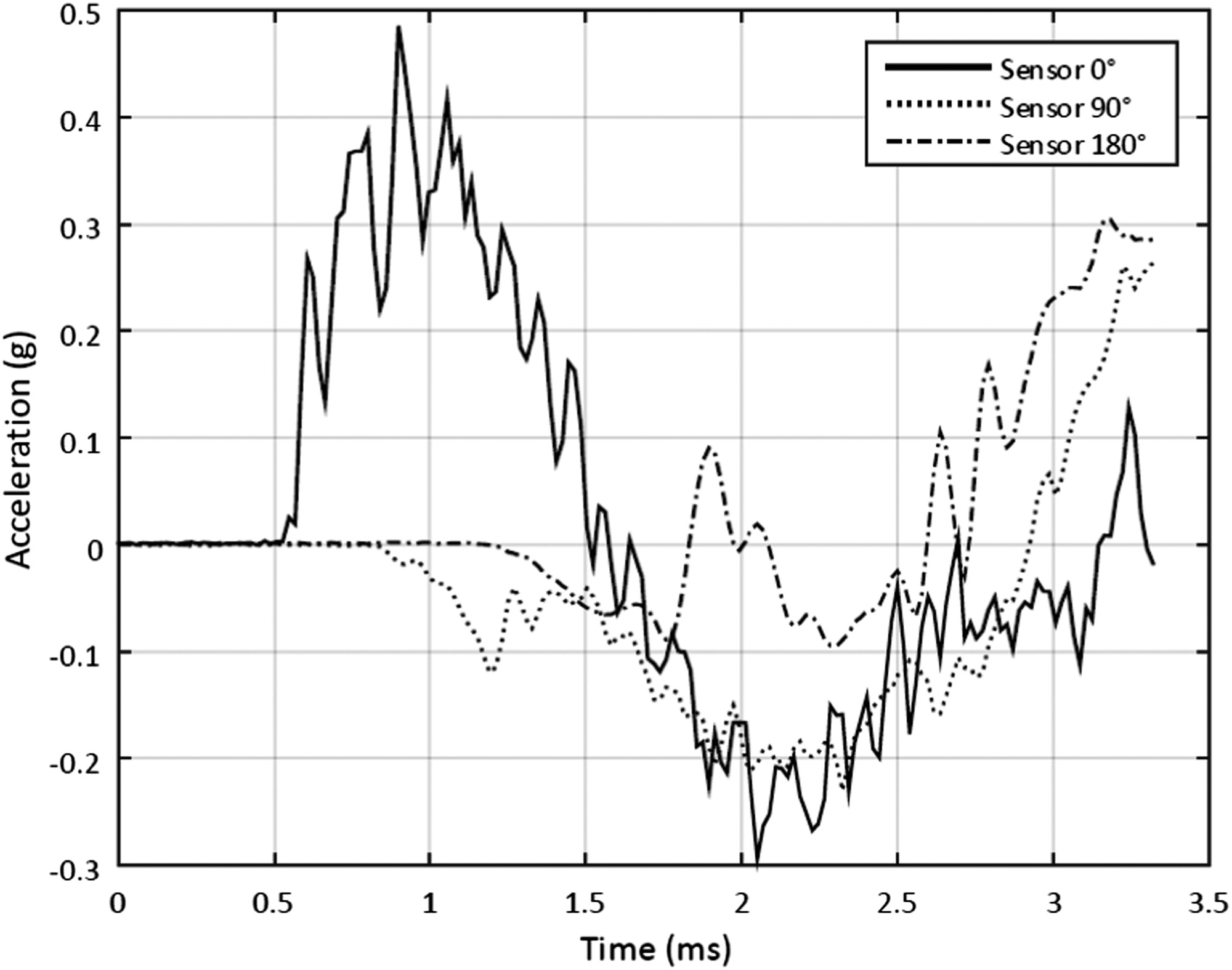 Fig. 2. Acceleration vs time of the 0°, 90° and 180° sensor position after excitation at 0°.
The measurements are summarised in Fig. 3 showing the mean delay and the standard deviation (assuming normally distributed results) for each sensor position. Thereby the maximum propagation delay , defined as the time the signal needs to cover half the perimeter, has a mean of 0.67 ms and a standard deviation of 0.02 ms. It was found that the phase difference of the vibration signal propagating along the perimeter between each transducer was constant, meaning a constant velocity of the signal. Thus, using the mean value obtained for , the mean propagation velocity is . This velocity lies between that of longitudinal () and shear waves () in steel [24]. It can thus be assumed that the measured wave is a mixture between these two waveforms and therefore represents a reasonable estimate.
 Fig. 3. Measured mean and standard deviation of the signal propagation delay vs length of propagation (sensor position).
To estimate the exact waveform, further investigation needs to be done, which is beyond the scope of this work. Further information on waveforms and the dependency of the propagation on the Lamé parameters can be found in [24,25]. It needs to be pointed out that the propagation velocity can vary (e.g., through the above-mentioned parameters). Once the propagation velocity for a particular application is known, the propagation delay can be calculated for a given distance by dividing by .
III.PHASE SHIFT MODELLING
This section provides a physical model-based approach to quantify the influence of the signal propagation delay on the super-positioned vibration signal at the transducer on the ring gear. Only the vibration of the ring-planet meshing and the signal propagation through the ring gear is taken into account, since the authors are interested in the time varying transfer path. Other modulation effects are not considered. Note that in addition to the N ring-planet meshes, a further N sun-planet meshes occur, and in the general case the latter are not in phase with the former [8], although this is often not taken into consideration. Such complexities are not considered in the current study, and are unlikely to change the results because, as noted by Parker and Lin [8], the relative phase between ring-planet and sun-planet meshes is identical for all planets, regardless of the mesh phasing relationships between the different planets. That is, this phenomenon does not create any additional modulation effect. Note, too, that in the context of propagation delay, signals generated at the sun-planet mesh point and transmitted to the transducer through the planet and ring gears would experience the same propagation delay as that experienced by the ring-planet signal but with an additional DC offset corresponding to the delay time through the planet. The effective phase modulation function of the ring- and sun-planet meshes is therefore identical, and it is thus reasonable to focus only on the ring-planet meshing case. Meanwhile, the alternative transmission path through the sun gear shaft and support bearings may produce a larger propagation delay, but one that is virtually constant, with no reason for large variations and hence no resulting phase modulation.
The vibration system is assumed to be linear, and so the effects of amplitude, frequency and phase modulation can be considered to be additive. This enables the investigation of the phase modulation as a separate effect on the vibration signal. The gear meshing of each planet is assumed to be in phase (although, as will be explained later, the results are applicable to other mesh phasing arrangements) and the planets are equally spaced around the ring gear. The notation is adopted from [12]. The gearmesh vibration at the source, the point on the ring gear where the meshing of planet occurs at time , is formulated as a co-sinusoidal signal, shown in eq. (1).
The degree of phase modulation in the signal is indicated by the modulation index , defined as the peak phase deviation around the unmodulated gearmesh vibration of planet . The modulation index can be expressed in terms of the maximum propagation delay relative to the time of one gearmesh period , in radians:
By knowing the modulation index, the time-varying behaviour of the gearmesh phase can be expressed as a function of , the rotational angular speed of the planet carrier, and , the angular position of planet around the ring gear, as shown in eq. (3). Since the propagation speed is assumed constant, the propagation delay will be at its maximum when the planet is directly opposite the transducer and will decrease linearly with carrier rotation angle until it reaches its minimum when the planet is directly under the transducer. This is repeated for every revolution of the planet carrier. For simplicity this linear increase and decrease of phase is approximated here using a sinusoid:
It should be noted that the true modulation index for the phase modulation in this instance is , since the phase is varying by up to around the mean phase, which itself is shifted by from the signal generated at the gearmesh point. That is, the modulation index is defined here as the maximum phase deviation of the measured signal around the unmodulated but phase-shifted gearmesh vibration of planet , and is equal to . The relationship between time waveform and unwrapped phase of an unmodulated and a (sinusoidal phase modulated) signal is shown in Fig. 4.
 Fig. 4. Schematic relationship between time waveform and unwrapped phase of an unmodulated signal xmi(t) and a signal xri(t), subject to sinusoidal phase modulation.
Note that the approximation of the triangular phase modulation curve with a sinusoid of the same magnitude slightly overstates the degree of modulation, since the first Fourier series coefficient of a triangle wave is times the amplitude of the latter. This approximation is made here because the true modulation curve would likely be something between a triangular wave and a sinusoid, and it is preferable to overstate an effect when testing its negligibility.
The vibration signal of planet at the transducer on the ring gear, including the phase modulation effect, can be described with eq. (4).
Summation of the phase modulated gearmesh vibration of all planets gives the complete measured signal, as shown in eq. (5).
where is the number of planets. The vibration signal can be transformed into eq. (6) with the use of Bessel functions of the first kind [6], denoted as , with being the order of sideband. It is also assumed that the amplitude of the vibration signal of each planet is equal () and does not change over the record length.To enable the analysis of the phase modulation effect in the amplitude spectrum, eq. (6) is rewritten in the frequency domain (only giving the positive frequency components):
Equation (7) notes that only sidebands spaced at the planet pass frequency, or times , the rotational speed of the carrier (and integer multiples of it), appear in the spectrum, as shown in Fig. 5. The amplitudes of the sidebands are defined by Bessel functions of the first kind. The order of the Bessel function is dependent only on the number of planets and the order of the sideband [26].
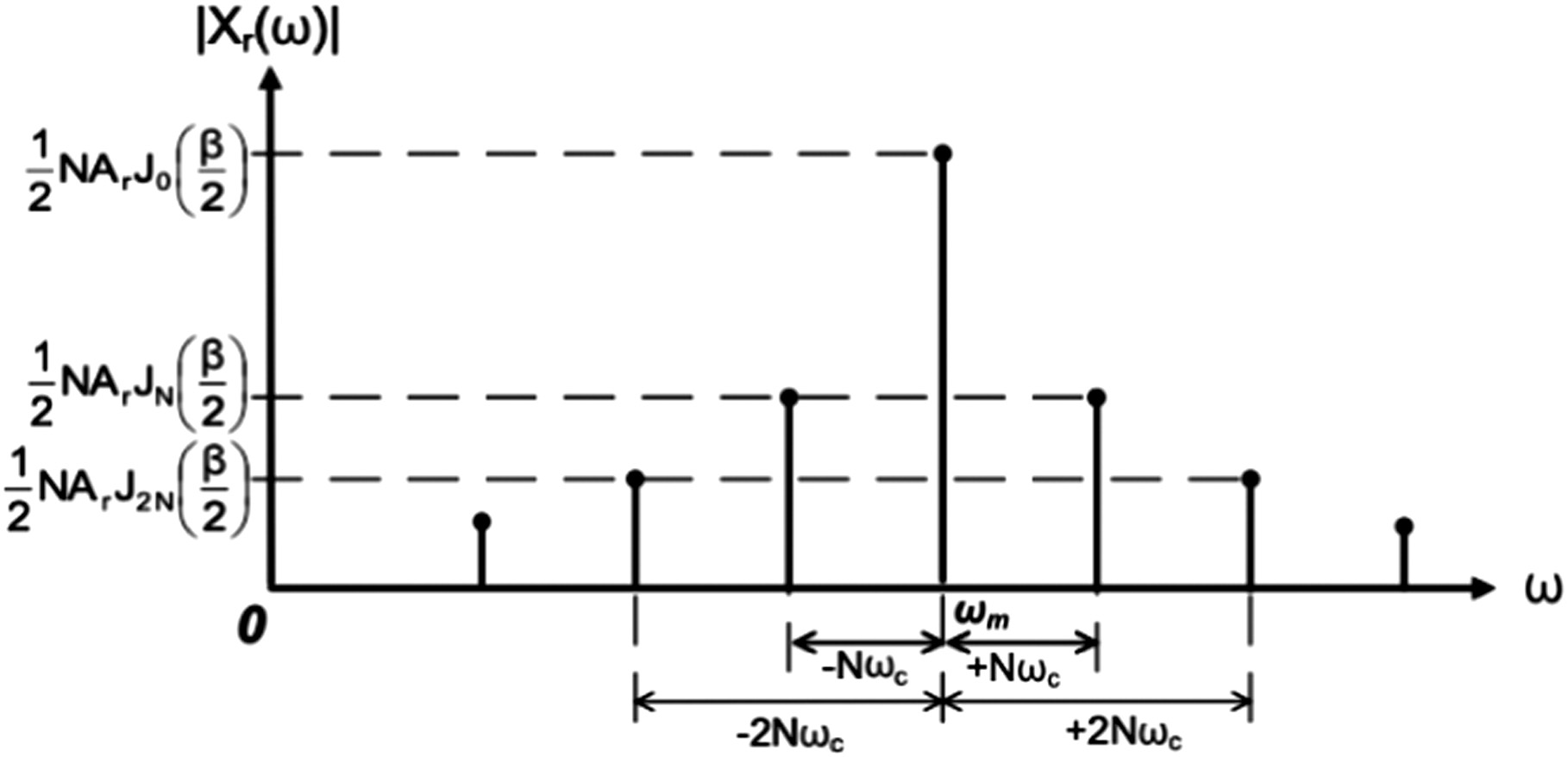 Fig. 5. Schematic single sided amplitude spectrum of a phase modulated vibration signal using eq. (7).
A central finding of this work is that for in-phase meshing, the ratio of the amplitude of the first order sideband due to propagation delay to the amplitude of the gearmesh component is given by . By defining this Bessel function relationship and by knowing that planetary gears are designed with planets, it follows that the amplitude of the sidebands due to propagation delay will always be small compared with the gearmesh frequency component and will decrease with increasing numbers of planets and the order of sidebands (for ). This is illustrated in Fig. 6, which shows the Bessel function of the first kind and order 0 (corresponding to the gearmesh component), and for orders planets (for the first order sidebands and for modulation index ). (Note that phase modulation, unlike amplitude modulation, causes an infinite number of sidebands even when the modulation function is a sinusoid.) While the derivation of an equivalent ratio for the common sequential phasing arrangement is not given here, it will be appreciated that the effect of propagation delay is similarly small in such cases. Inalpolat and Kahraman [3] show a number of in-phase and sequential meshing cases, and they demonstrate that in the sequential case the amplitude of near-gearmesh planet-pass harmonics is lower than the gearmesh component of the in-phase case, but by no more than 2 dB in their examples (cf. Figs. 3 and 4 in [3]). The derivations above will be applied to a number of industrial examples in the following sections.
 Fig. 6. Bessel function of the first kind for orders 0 and N= 3, 4 and 5 planets (indicates relative amplitude of gear mesh and first order sideband components, respectively) for modulation index β2.
IV.EFFECT OF PROPAGATION DELAY ON VIBRATION ANALYSIS
A.EFFECT ON A HELICOPTER MAIN ROTOR TRANSMISSION
This section uses an example to analyse the effect of the phase modulation on the evaluation of the gearbox condition based on vibration signals. The example is a gearbox from the OH-58A Kiowa helicopter main rotor transmission, with three planets (), a ring gear with Zr = 99 teeth and a diameter of mm. Assuming a propagation velocity of (cf. Section II), the maximum propagation delay is given by . If the planet carrier of the gearbox is rotating at , eq. (2) can be used to calculate the modulation index for one planet-ring gearmesh vibration. The time-varying phase of each planet can then be calculated and used to obtain the vibration from each planet-ring gearmesh transmitted to the transducer . The three planet vibration signals , and are then added to obtain the complete vibration signal , which represents the signal measured by the transducer on the ring gear. These signals – , , and – are shown in Fig. 7 for one carrier revolution.
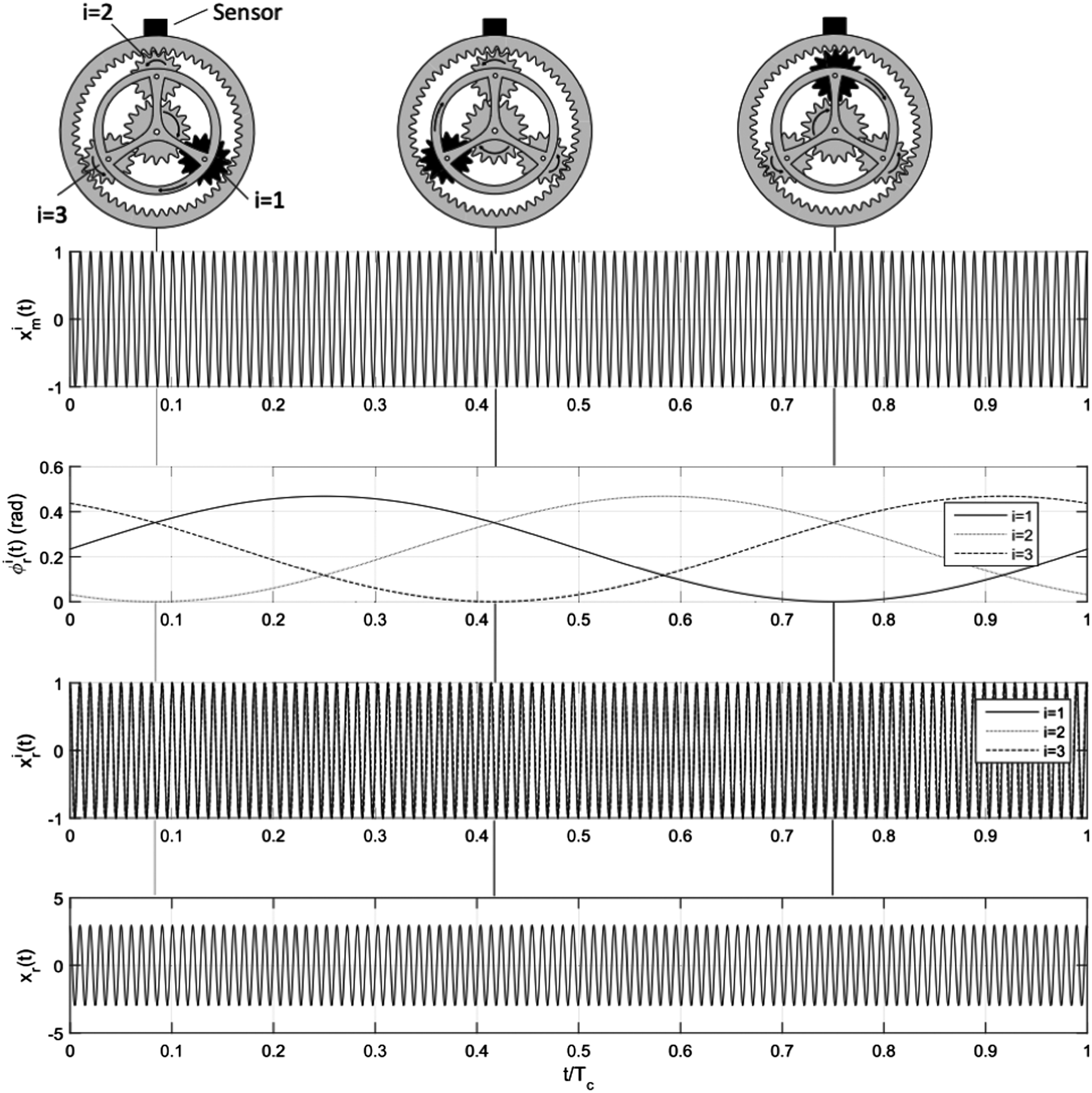 Fig. 7. Phase modulated vibration signals of a planetary gearbox (transducer mounted at the top of the ring gear) with β2=0.23, Zr=99 and N=3 for one revolution of the planet carrier. The movement of planet i=1 (black planet) is marked in the top diagram.
In practice, to analyse the condition of a gearbox, the vibration signal is often transformed into the frequency domain, and the amplitude spectrum used to assess the gearbox condition [7]. One feature of interest in the spectrum is the presence (and distribution) of sidebands around the gearmesh frequency, which are caused by amplitude and/or phase modulation and can give an indication of the condition of the gearbox. The two questions investigated here are: (a) “with the given gearbox parameters, what are the amplitudes and frequencies of the sidebands caused by phase modulation from propagation delay?”, and (b) “can this modulation interfere with condition assessment based on the analysis of sidebands around the gear mesh frequency?”. To answer question (a) the overall vibration signal (eq. (5)) is transformed into the frequency domain (eq. (7)), and the amplitude spectrum shown in Fig. 8 is obtained. It can be seen that the component at gear mesh frequency is clearly dominant in the spectrum. This is due to the gearbox having the planet-ring gear meshing in phase, equally spaced planets [1] and a sufficiently small modulation index As with Fig. 5, it can also be seen that sidebands at a distance of (and harmonics ) around the gearmesh frequency occur.
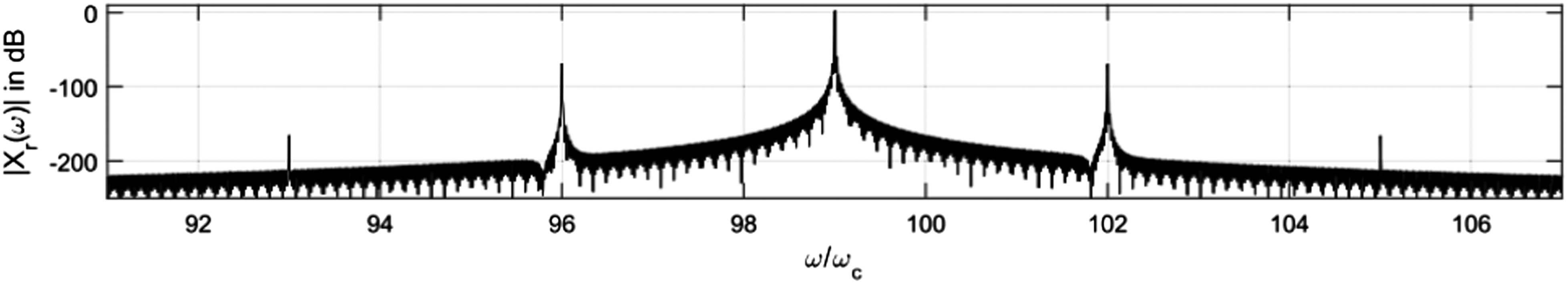 Fig. 8. Amplitude spectrum of phase modulated vibration signals of a planetary gearbox (transducer mounted at the top of the ring gear) with β2=0.23, Zr=99 and N=3.
Utilising Carson’s bandwidth rule [27] for phase modulation, it is clear that for practical considerations only the first order sidebands need to be considered to include most of the sideband energy. Thus, to evaluate the effect of the phase modulation in the in-phase meshing case, the ratio in dB of the amplitude of the first order sideband to that of the gearmesh frequency is used, as defined in eq. (8). The ratio is referred to as the spectral modulation ratio.
For the given example, ratior = −71 dB.
To answer question (b) on the potential impact of this effect on condition assessment, note that the sidebands occur at multiples of the planet pass frequency, , around the gearmesh frequency, and hence would coincide with other sidebands from this common modulation frequency. McFadden and Smith [1] point out that amplitude modulation at this frequency is to be expected regardless of gearbox condition, but a ring gear fault would also produce (amplitude and/or phase/frequency) modulation at this frequency. Yet, while the modulation frequency from propagation delay coincides with these other phenomena, the amplitude of the sidebands is very small with ratior = −71 dB, or about the resolution offered by a 12-bit analogue-to-digital converter and certainly many times smaller than the sidebands expected from typical amplitude modulation in planetary gearboxes [1,3]. It therefore seems quite likely, based on this example, that for practical purposes the time propagation delay can indeed be neglected. Further examples are investigated below.
B.EFFECT ON INDUSTRIAL GEARBOXES
This section extends the previous results to a wider range of gearboxes, to investigate whether the phase modulation effect has a significant influence on the vibration analysis of typical planetary gearboxes. Table I shows the parameters and analysis results for a number of industrial gearboxes.
Table I. Results on planetary gearboxes of wind turbines (gearbox no. 1 and 2), helicopter transmission (no. 3), turboprop reduction gearbox (no. 4) and industrial gearbox (no. 5).
| Symbol | Unit | Planetary gearbox model | ||||
|---|---|---|---|---|---|---|
| no. 1 | no. 2 [ | no. 3 [ | no. 4 [ | no. 5 [ | ||
| 3 | 3 | 3 | 5 | 3 | ||
| 138 | 99 | 99 | 100 | 72 | ||
| 1118 | 1016 | 305 | 212 | 105 | ||
| 1756 | 1596 | 479 | 333 | 165 | ||
| 75 | 22.2 | 451 | 1021 | 1500 | ||
| 7.85 | 2.32 | 47.2 | 106.9 | 157.1 | ||
| 1084 | 230 | 4676 | 10,692 | 11,310 | ||
| 0.37 | 0.33 | 0.10 | 0.07 | 0.06 | ||
| 0.20 | 0.04 | 0.23 | 0.37 | 0.20 | ||
| − | − | − | − | − | ||
The top half of Table I shows the parameters of the considered planetary gearboxes. The list includes: wind turbine gearboxes (numbers 1 and 2); a helicopter main rotor gearbox (OH-58 A Kiowa, no. 3); a turboprop reduction gearbox (T56/501, no. 4); and a gearbox for general industrial applications (Vogel P04, no. 5). All gearboxes are noted to have in-phase planet-ring gear meshing and equally spaced planets. The gearboxes have been used in numerous publications for vibration analysis purposes. The lower half of the table displays the parameters of the gearboxes for estimating the phase modulation effect, calculated using the equations from Section III. It is assumed that in all cases. It can be seen that all researched gearboxes exhibit phase modulation that can be considered narrowband since the modulation index is sufficiently small, i.e., .
The results of (bottom row) show that there is no significant impact of the phase modulation on the amplitude spectrum. All ratios are lower than dB and therefore multiple times lower than the sidebands considered in the publications of McFadden and Smith [1], Inalpolat and Kahraman [3], Molina Vicuña [12] and others. While these examples all have in-phase meshing, as noted in Section III the net effect on sequentially phased gearboxes would be very similar – likely within 2 dB of the results presented here due to the comparable amplitudes of the most dominant spectral components in the in-phase and sequential meshing cases.
C.SENSITIVITY ANALYSIS
1)MODULATION INDEX
Figure 9 shows the spectral modulation ratio versus modulation index for 3, 4 and 5 planets. It can be seen here that even for the worst-case scenario of and a (very high) modulation index of , the amplitude of the sidebands is negligible, with a around dB.
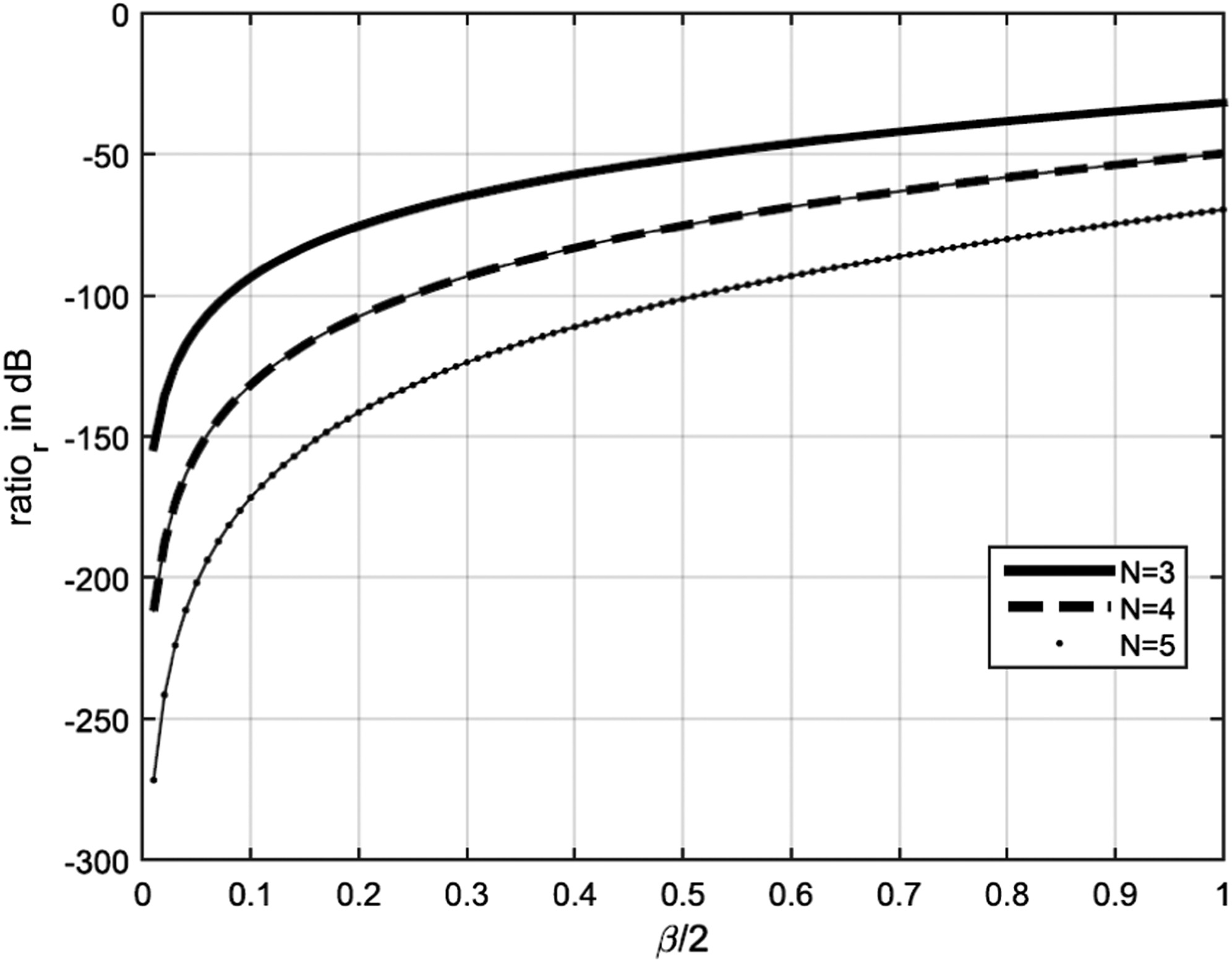 Fig. 9. Spectral modulation ratio vs modulation index β2 for N= 3, 4 and 5 planets.
2)ROTATIONAL ANGULAR SPEED OF THE PLANET CARRIER
Figure 10 shows the effect of planet carrier speed on , and it can be seen that even when the speed of the carrier is two times higher than the rated speed of the gearbox, the ratio remains below dB and can thus be considered negligible for spectral analysis in practical applications.
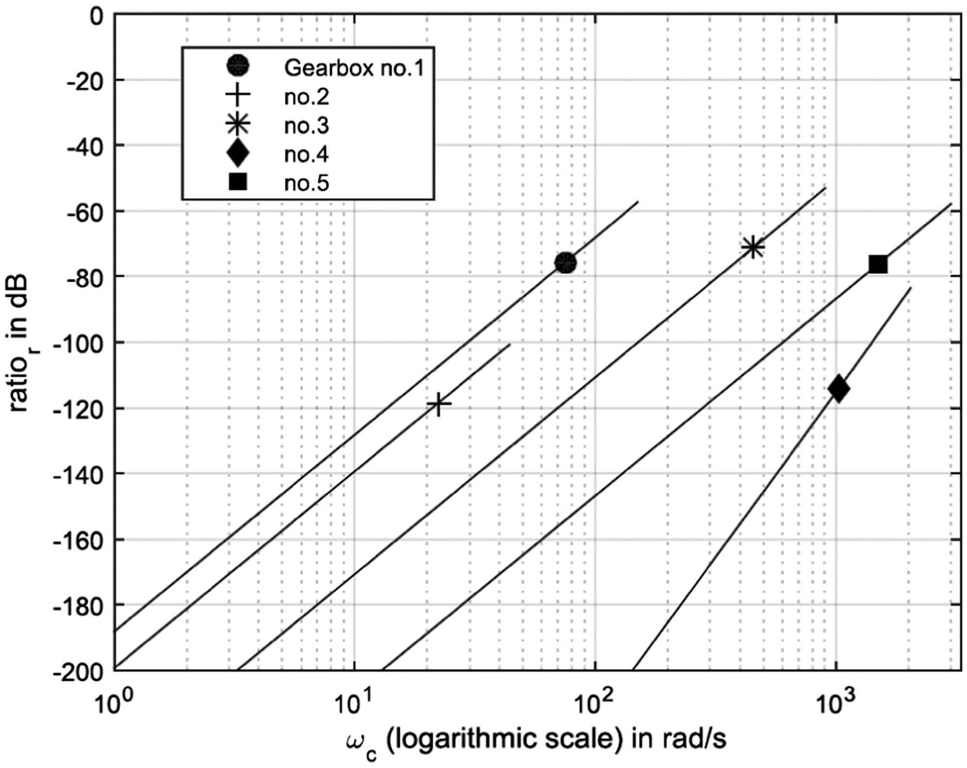 Fig. 10. Spectral modulation ratio for planet carrier speeds up to two times the rated value for the gearboxes in Table I. The markers show the rated speed of that specific gearbox.
3)SIGNAL PROPAGATION VELOCITY
As outlined in Section III, the propagation velocity of the vibration signal through the tested ring gear was determined by experiment to be . The parameter will differ between gearbox models since it is dependent on the variables mentioned in Section II. Therefore, the sensitivity of to the propagation velocity is investigated in this section. Figure 10 shows for signal propagation velocities of 50% of the measured value (). It can be seen that even with very low propagation velocity, the spectral modulation ratio is still not significant, remaining below dB for all gearboxes analysed. The resulting sidebands would thus have virtually no impact on the evaluation of the amplitude spectrum.
4)BOUNDARY REGIONS OF CARRIER SPEED AND RING GEAR SIZE FOR NEGLIGIBLE PROPAGATION DELAY
To indicate more clearly the conditions under which the propagation delay can be neglected, analysis was undertaken of a hypothetical gearbox with conservative parameter settings , m/s (pure shear wave velocity in steel [24]) and . These parameters were chosen to represent the most problematic values (i.e., giving the largest propagation delay effect) likely to be encountered. Values for of dB and dB were selected to represent conditions for which the delay phenomenon might and very likely would affect the diagnostic analysis, respectively. The combinations of carrier speed and ring gear diameter giving these values were then calculated, with the results plotted in Fig. 12. For context, also plotted in Fig. 12 are the carrier speed and ring diameter values corresponding to the gearboxes in Table I, but note that the other parameters are in general different to those gearboxes, the aim being to produce results on the more conservative side. For cases that fall below the dashed line, the propagation delay can be confidently neglected, so for example a gearbox with three planets and a 1-metre diameter ring would have to operate with a carrier speed greater than 40 rad/s before the delay might affect the analysis, and at 60 rad/s before the delay is very likely to affect the analysis (within the limitations of the chosen parameter values).
 Fig. 11. Spectral modulation ratio for different propagation velocities for the gearboxes in Table I. The markers show the measured propagation velocity from Section II.
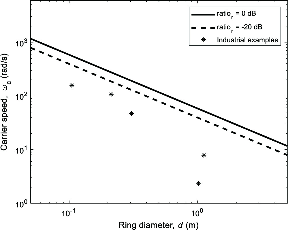 Fig. 12. Boundary regions for carrier speed and ring gear size: lines indicate boundary above which diagnostic analysis might (ratior=−20 dB) and very likely would (ratior=0 dB)) be affected. Parameters used: N=3, v=3230 m/s and Zr=150. Industrial examples represent rated carrier speed and ring gear size from Table I, but other parameter settings (N, v and Zr) do not in general correspond to those examples.
It can be seen that the delay is clearly negligible for all the examples from Table I, supporting the analysis of earlier sections.
V.CONCLUSION
This paper sought to investigate the common assumption that the signal propagation delay can be neglected when analysing vibration signals from planetary gearboxes. A model of the gearmesh vibration was constructed to illustrate the effect of the propagation delay, and an experimentally obtained value of the speed of propagation through the ring gear was used to quantify the effect for a number of commercial gearboxes. It was shown that the delay causes a periodic phase modulation of the gearmesh signal as measured by a sensor fixed on the ring gear, and that the resulting sidebands around the gearmesh frequency in the amplitude spectrum occur at multiples of the planet pass frequency. This corresponds to one of the main amplitude modulation frequencies in planetary gearboxes, regardless of condition, but also to the frequency of modulation arising from a fault on the ring gear, and so could conceivably interfere with diagnostic analysis.
To quantify the effect of the delay, the resulting sideband structure was analysed, and a spectral modulation ratio was defined for in-phase meshing gearboxes as the ratio of the amplitude of one of the first-order sidebands to that of the gearmesh component. By making several conservative assumptions, it was shown that the ratio can be simplified to a ratio of Bessel functions of the first kind, with the order determined by the number of planets. The ratio is thus entirely defined by the number of planets and the modulation index, the latter of which is proportional to the gearmesh frequency and diameter of the ring gear, and inversely proportional to the propagation velocity. By knowing that planetary gearboxes are designed with planets, it was shown that for realistic gearbox parameters the amplitude of the sidebands due to propagation delay will always be small compared with the gearmesh frequency component and will decrease with increasing numbers of planets and the order of sidebands (for modulation index ). While not investigated explicitly in this paper, it was explained that very similar results would be obtained for the common sequential meshing case, but with respect to the strongest planet-pass harmonic rather than gearmesh component, and so the conclusions also apply to such gearboxes.
For all five commercial gearboxes studied, the ratio was found to be below dB, and it was shown that it will remain below dB as long as the modulation index is less than 1, which would seem the case in virtually all applications. It is thus concluded that for practical purposes the common assumption is correct, and the signal propagation delay can indeed be neglected.