I.INTRODUCTION
The use of small robotic inspection platforms continues to revolutionize the inspection of spaces inaccessible to humans, such as certain aspects of sewer pipe network infrastructure, or potentially delicate archaeological sites. If a human is unable to easily access a specific area, assessing that environment for faults and damage can prove challenging. A small robotic platform can be deployed through otherwise challenging access points and explore these environments safely and efficiently, minimizing its influence on its surroundings. These robots can also be designed at varying scales and layouts to ideally suit specific tasks. However, this can be a potentially laborious process. Not only may a new design need to be produced to match each specification, but sourcing ideal components and assembling these can complicate the development process.
The use of additive manufacture or 3D printing can aid in this procedure. 3D printing can allow for the production of complex mechanical structures quickly and efficiently, including moving mechanisms that require no assembly on manufacturing completion [1]. This is an advantage over more traditional construction types, where subtractive manufacture methods may prove more complex and require further assembly. This has led to an increase in production of Non-Assembly robots, which explore the capabilities of this process as a means to produce locomotion.
3D printing and Non-Assembly mechanisms have been utilized in a wide range of areas. The process has been applied to producing prosthetic limbs for those in developing countries [2] as well as for use in creating novel compliant medical devices [3] and rehabilitation exoskeleton devices [4]. Models of creatures, such as elephants and caterpillars, with moveable joints and soft elements have also been produced using the method [5–7], as well as reproductions of human spines [8]. Various types of joints and actuators have also been produced with 3D printing, using a range of materials, including metal universal joints [9], artificial rubber-based series elastic elements (SEEs) [10], flexible pneumatic and hydraulic actuators [11–13], sprung joints [14], shape memory materials [15], and full complement bearing joints [16]. Origami-style robots designed to function as medical gripping arms have been produced with Non-Assembly techniques [17], and work has been performed to explore 3D printing shapes around required electromechanical components, such as a propeller motor in a model plane [18].
Non-Assembly mechanisms have been created through additive manufacturing processes [19] including previous work within the author’s institute, design of a small, 3D-printed, Non-Assembly robot that locomotes with a linkage-based walking mechanism [20]. This robot was designed to explore difficult-to-access areas. This system utilized a 3D-printed shell with a geared mechanism and additional linkages to produce a hexapod walking robot driven by two single degree-of-freedom (DoFs) mechanisms or one DoF per side. This demonstrated the ability to produce small, complex Non-Assembly mechanisms for small inspections robots utilizing 3D printing. However, the design of the robot presented some performance deficits. The small size prevented the use of encoders and produced large joint tolerances relative to the robot scale, making locomotion gaits inaccurate, resulting in unreliable movement trajectories. Furthermore, the nature of the mechanism resulted in increased postprocessing difficulties as well as delicate components that could become damaged in rugged environments.
This paper will introduce the next iteration of this robot and aim to improve the rugidization of the robot in a manner that will improve postprocessing and robot performance. This is achieved by introducing a more robust locomotion mechanism that provides a more reliable walking gait. This mechanism, and robot, is directly compared to the previous version, with identical experimentation to display the changes to performance.
II.WALKING ROBOT DESIGN
A.WALKING MECHANISM DESIGN
The proposed mechanism presented is an improvement of the previously presented work [20] as shown in Fig. 1, which used an embedded microcontroller (A) controlled wirelessly over Bluetooth (B) with a 2S lithium polymer (LiPo) battery (C). The robot used a crank and slider mechanism (E) to drive a central leg (F), with passive rocker legs (D) either side driven by linkages (G).
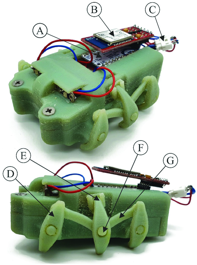 Fig. 1. Jackson-Mills et al. 3D-printed walker robot, 2021 [20].
The previous design displayed a typical hexapod design with three legs on each side. The one-DoF walking mechanism was first developed using a linkage system and has now been refined to produce a more desirable gait. Computer-aided design (CAD) software was used for detailed design of the mechanism and to perform a motion study. Modifications were made to the legs, giving them a curved profile that allows more efficient space utilization in cylindrical access points. The previous Non-Assembly linkage system presented in Fig. 2 is driven through a single crank in the central leg (Fig. 2, D); with only 1 DoF, the gait cycle was fully defined during the mechanism design stage. Each bevel crank (D/E) is supported at either end in plastic to plastic contact. The front and back legs are driven via links (B) attached to the crank on the middle leg such that they move in a rocking motion pivoting on chassis pins (A). The prismatic slider, which is paired with the central leg (C), achieves the stepping motion required by forcing linear movement of the central leg from a defined point of rotation. The points of one motion cycle (1–4), displayed in Fig. 2 occur at 0° (1/Orange), 90° (2/Yellow), 180° (3/Pink), and 270° (4/Blue). The step lengths are calculated from the CAD model. The sum of and provides the total movement of the robot per crank revolution, . This leads to .
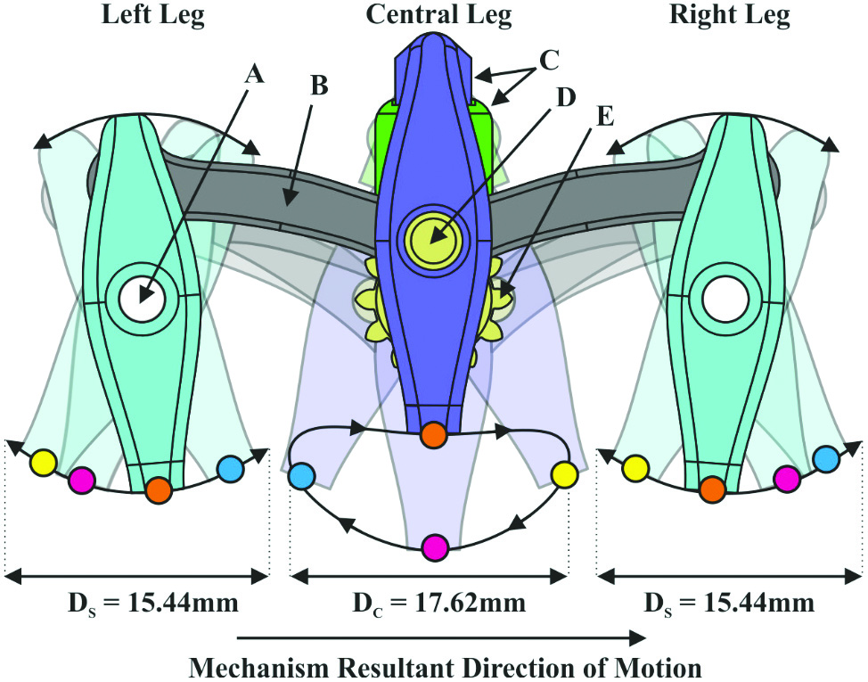 Fig. 2. The previous iteration of the Non-Assembly one-DoF leg mechanism where the numbered and colored circles show the positions of each leg on their respective paths at 0° (1/Orange), 90° (2/Yellow), 180° (3/Pink), and 270° (4/Blue) [20].
The latest design iteration improves the previous work by removing the left and right linkage “rocker” legs which had shorter step lengths than the central crank, as well as a lower sweep height which kept the robot chassis from being lifted clear of obstacles. The left and right rocker legs have now been replaced with crank legs identical to the design of the central leg. They are mechanically linked by a gear train to be 180° out of phase with each other. A CAD model of the updated locomotion mechanism can be seen in Fig. 3. The new mechanism is larger, a 27.79-mm precise step in the CAD model versus the previous design results in a 57% increased step distance versus the central leg alone and 80% versus the rocker legs. As the total movement per crank turn, , is now multiplied by 2 for the new design, .
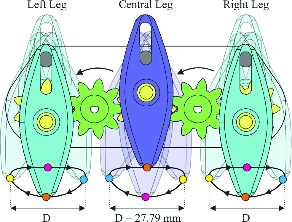 Fig. 3. The next iteration of the one DoF Non-Assembly leg mechanism, using the same gait system as the central leg of the previous design.
A major design improvement is the removal of the prismatic slider, which was an integral part of the previous crank slider central leg mechanism [20] as shown in green and labeled C/D in Fig. 2. The leg motion still relies on sliding, however, instead of the slider being a separate rotational part, there is now a pin on the chassis. The slider is now a slot on the leg instead of a track system which is printed in situ, locked with the leg slider. This removes the need for the slider as a separate part but allows an identical motion. As a result, the robot no longer needs to be assembled in two halves to pair the slider and leg. A motion analysis study of the legs was undertaken, showing the displacement of the “foot” on each leg of the two walking mechanisms as shown in Fig. 4. Each displacement path corresponds to the numbered paths taken by the foot of each leg highlighted on the CAD models in their respective figures.
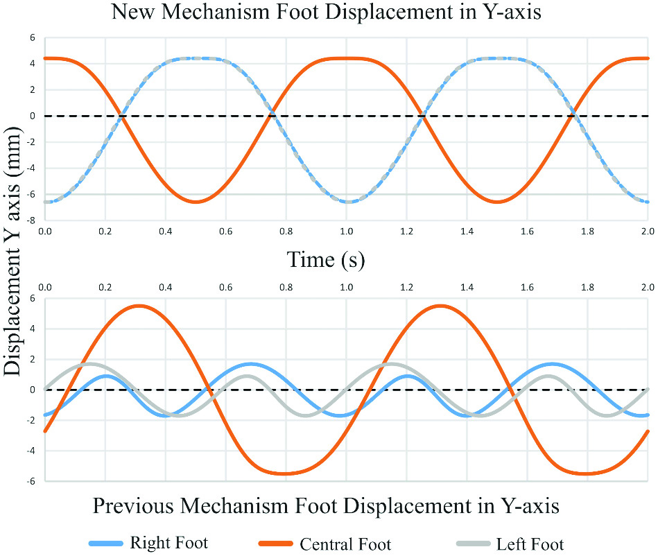 Fig. 4. Simulation of the latest iteration of the robot walking mechanism against the simulation of the previous iteration of the robot mechanism [20].
The simulation in Fig. 4 highlights the key improvements of the new mechanism design: a standardized step height across all three legs, prefect antiphase of 180° between the central and side legs, and an exaggerated step height of 8 mm from the crossing points of the legs paths.
B.WALKING MECHANISM ACTUATION
Due to the alterations of the robot mechanism from the previous iteration’s linkage-based system to a gear train design, new design parameters had to be considered. The gear train consists of five custom-designed nine-tooth gears which have been optimized for maximum gear tooth strength as shown in Fig. 5. The optimization of tooth strength has been carried out by using parametric gear design in CAD to minimize the number of teeth of the spur gears and to maximize the gear module. This results in a smaller ratio of teeth to diameter. As well as this, the pressure angle of the gears has been increased to 30 degrees. This modifies the geometry of the gear model such that the gear tooth thickness at the base of the teeth is increased versus a standard 20-degree profile. Gear tooth strength is favored in this Non-Assembly gear train over reduced noise: a benefit of lower pressure angle designs. Reduced noise in this scenario is not useful, whereas the printed acrylonitrile butadiene styrene (ABS) gear teeth are crucial to the movement of the entire mechanism. Should one fail, the one-DoF mechanism and hence the three antiphase legs would become out of sync or be rendered immovable. The size of the gears was determined by the Objet 1000 printer’s Non-Assembly tolerance of 0.2 mm [20]. An optimal pitch circle diameter (PCD) of gear was found where the mesh distance between gear teeth in a noncontact state was 0.2 mm on both sides of the driving teeth in the CAD model (C in Fig. 5). To achieve the desired motion output of three crank shafts (yellow gears shown B/D/E) with an identical rotation direction, a minimum gear train of 5 must be used. Transmission is achieved through a printed D-shaft hole (A) which connects directly to the motor output shaft. Each of the gears sit in the chassis housing on shaft bosses (examples D/F). End caps on the cranks (E) fasten the Non-Assembly legs while allowing rotation.
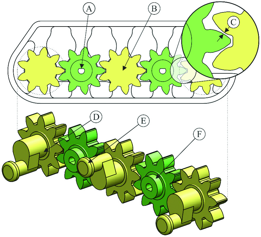 Fig. 5. Gear train design as it is configured before being generated as a printable STL file and final 3D assembly of the gear train model with crank shafts (chassis and shaft housings are hidden).
III.ROBOT MANUFACTURE
Manufacture of the final robot used for testing includes generation of the STL file, printing the robot, postprocessing, and then assembling the electronics package.
A.PRINTING THE NON-ASSEMBLY MECHANISM
Figure 6 shows the completed CAD model of the robot in the configuration used to generate the STL used in printing with the electronics motor mounting points now on show (A). A cross-sectional view has been generated to show the left mechanism cut away along the axes of key rotation parts and shafts. These include the pin rocker (B), the central leg crank (Yellow, D), the idler driven gears (Green, C), and the crank rotation within the robot leg (E). In the final design, each shaft (E) is mated concentrically with a hole of diameter of the shaft + 0.2 mm (F).
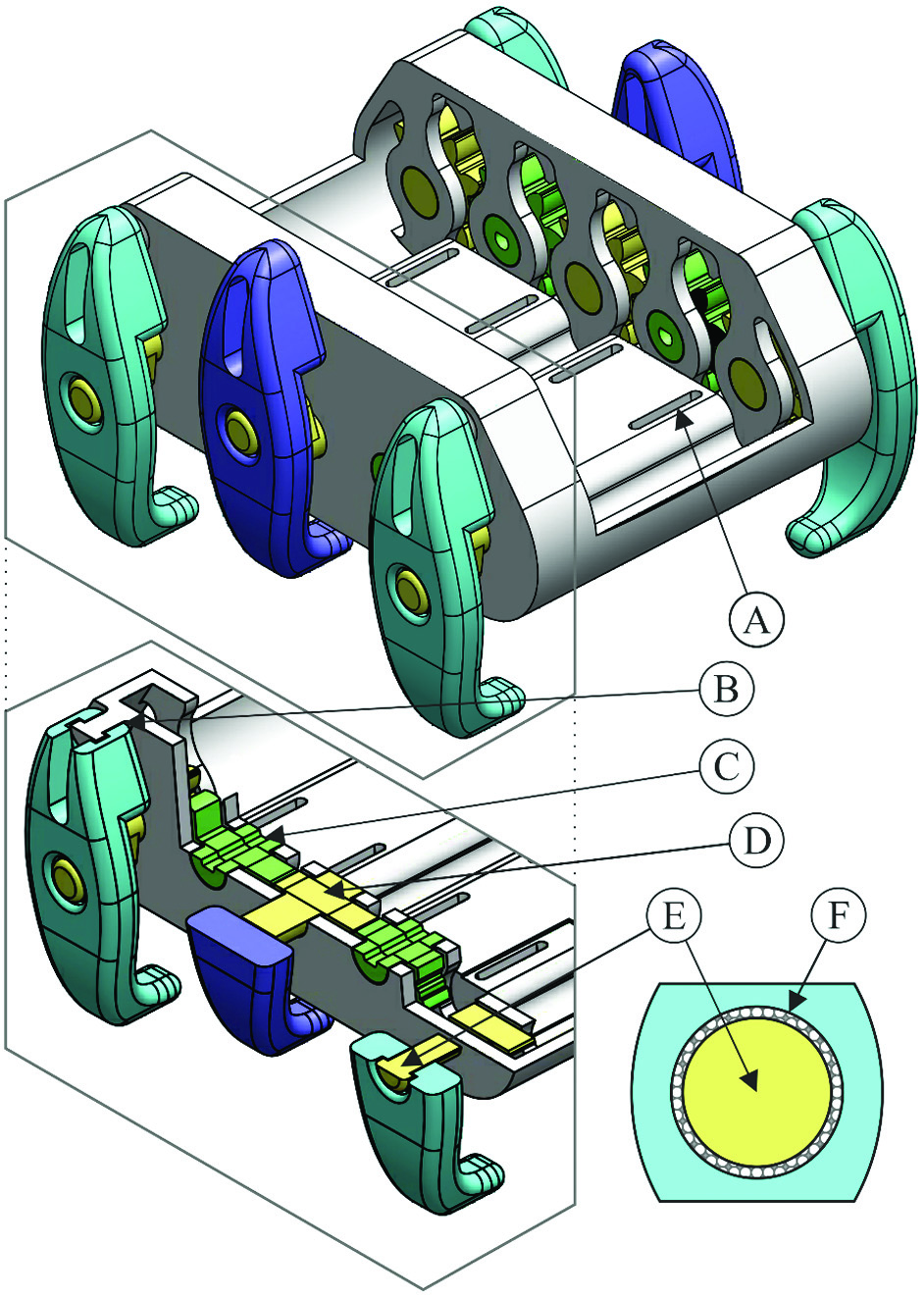 Fig. 6. CAD model designed for Non-Assembly with tolerance cut-away cross section and shaft example.
B.CLEANING AND COMPONENT MOUNTING
The robot was printed using the Objet’s digital ABS material, and the total printing time for one robot was 12 hours. Assembly first requires the removal of support material from the finished printed parts. The Objet printer used SUP705 gel-like photopolymer as its support material, which is printed in any negative space to separate solid objects in the assembly. This requires cleaning to clear the moving parts in the legs, slot (D), and shaft (E), as the support is not dissolvable and requires manual removal. More detail on the manufacturing method is available in Jackson-Mills et al. [20]. The cleaned robot is shown in Fig. 7 with the addition of motor and desired electronics packages (B/C) and markers for motion tracking (A). The MicroMetal Motors used to drive the system are inserted into the D-shaft mechanism gears, as shown in Fig. 5. Motor mount caps are then screwed into slots on the robot to locate the motors and fully define the system.
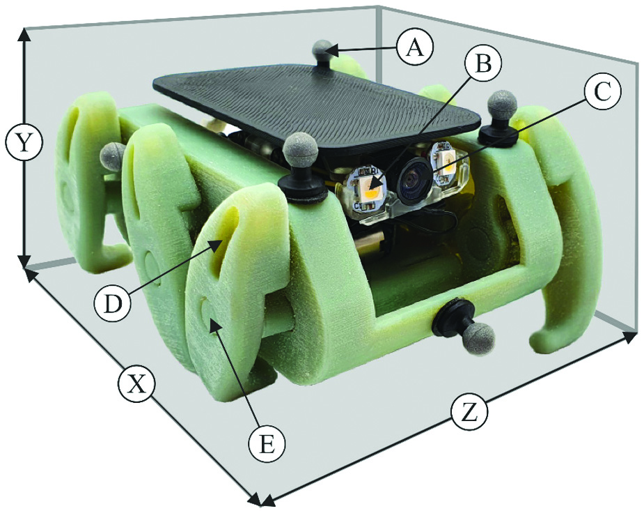 Fig. 7. Final 3D-printed model, with dimensions of the robot displayed, where XYZ = 105 × 55 × 90 mm.
C.CONTROL SYSTEM DESIGN OVERVIEW
The electronic components and control system of this robot have been altered from the previous robot. The robot still uses two Pololu MicroMetal gear motors to drive the separate sets of legs. However, unlike the previous version of the robot, these motors have encoders mounted to allow for feedback of the rotation of each motor. The custom control system utilizes an ESP-32 microcontroller with companion board, which includes motor controllers, a camera, lighting, and a six DoF Internal Measurement Unit (IMU), to allow for data collection as well as the potential for autonomous operation. The system operates using a lightweight version of robot operating system (ROS), micro-ROS, which uses a proportional integral derivative (PID) controller utilizing the encoder data to control the speed of the output motors. The system is powered by a 1-cell LiPo battery, with the voltage for the motors stepped up to 5 V on the companion board.
IV.ROBOT PERFORMANCE AND DISCUSSION
To compare the robot to the first iteration of the robot, the previous testing environment that was used for the first robot was recreated. The robot traveled over a set distance, with tracking data recording the trajectory of the robot to analyze the stability and reliability of the system. Tracking data were collected using OptiTrack Prime 13W cameras. The results of testing are shown in Fig. 8.
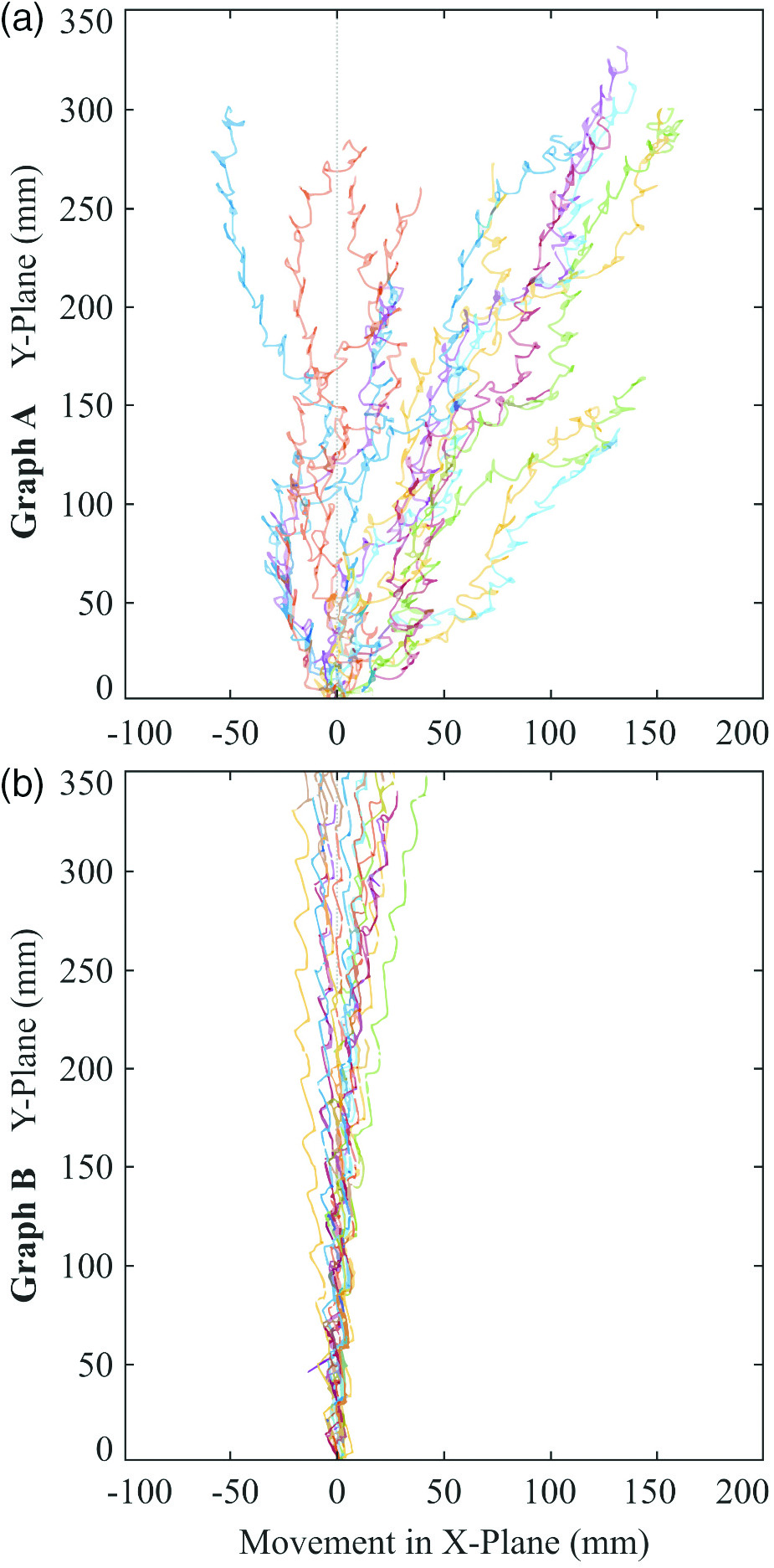 Fig. 8. Sixteen straight path trajectories graphs in mm. (a) Original 3D-printed walker robot. (b) New 3D-printed walker robot.
In the performance tests, the robot was controlled to travel directly forward for approximately 300 mm, to match the experimentation of the original robot. This took approximately 14 seconds to complete the positional data along the ground plane (X, Y) and was then collected. The test was then repeated 16 times. The 16 iterations or trajectory data are shown in Fig. 8b, with Fig. 8a displaying the matching results from the original robot. It can be clearly seen from Fig. 8 that the straight-line trajectory of the new 3D-printed robot is much more repeatable than the original robot. The original robot had an X offset of between approximately −50 mm and −150 mm after 300 mm of traveling in the Y axis, whereas the new robot’s equivalent offset was between approximately −25 mm and 40 mm. This equates to a range improvement of approximately 65%. It is also noticeable from Fig. 8 that the trajectories of the newer robot are far straighter than the original robot. This improvement in reliability is due to a number of key improvements to the robot.
The original robot did not use encoders to assist in the control of the leg speed of either side of the robot. Despite both motors running from identical pulse-width modulation (PWM) signals, one set of legs is moving faster than the other set due to variance in the performance of the two drive motors. This caused the robot to veer from the intended trajectory. The new robot now has the addition of encoded motors, which are controlled using a PID controller implemented in micro-ROS. This means that the motors are run at identical speeds, leading to the number of steps from either side of the robot equaling each other. The new mechanism also provides an improved walking gait. As highlighted in Fig. 2, the front and back legs of the original mechanism did not move perfectly in phase with each other. This resulted in the legs sliding slightly when interacting with the ground. The amplitude of the motion path of the outer legs was also different to that of the middle leg on the opposite side of the robot. This imperfection in the mechanism led to a rolling motion and foot sliding, which caused the robot to veer off track. As shown in Fig. 4, the new gait allows for the outer legs to move in phase with each other, and at the same amplitude as the middle leg on the opposite side, producing an improved gait. The new robot is also larger than the previous robot but had the same tolerances at each pivot point. This resulted in a smaller relative tolerance in relation to the robot’s size, which may have also assisted in the new robot’s improved performance.
One of the main intentions of utilizing a Non-Assembly mechanism is to optimize the construction process by minimizing assembly time. This is achieved by obeying certain principles during the design process. To produce a version of this robot with assembly mechanisms in place would require a complete redesign of the robot, where certain choices that had been made for the Non-Assembly mechanism would not occur. Therefore, a full assembly version could not be built to draw a direct comparison between the two design methods. However, all mechanical and structural components for an assembly-based robot would still need printing, so it is reasonable to assume that design and manufacturing times would be similar. The benefit of Non-Assembly methods is that following the manufacturing stage for the robot presented in this paper, there is no need for other fastening mechanisms and components to be bought and assembled. With small robots, this can often be difficult and time-consuming, so to be able to remove this stage is more time efficient and removes the requirement for additional component and equipment access. A limitation of the method is as the design requires PolyJet printers such as the Objet 1000 or similar, the materials of manufacture are limited to their material library.
There are still imperfections in the new robots performance. The trajectories for the new robot still have a small range of error, and a slight curve can be noticed in some of the trajectory samples. This could be in relation to a few factors. When placing the robot at the start of the test, it is likely that there will have been slight variations in the start orientation that could account for some error. Furthermore, when the robot is traveling forward, the opposite sets of legs should run 180° out of phase with each other. This would result in the middle leg on the right side moving in phase with the outer legs on the left side, and vice versa, to produce a typical hexapod gait. However, these positions are set manually when locating the motors within the mechanism. This is a point where potential inaccuracies could enter the system and, combined with errors introduced by the 0.2-mm tolerances, could cause flaws in the locomotion mechanism.
V.CONCLUSION
This paper presented a new iteration in the series of one-DoF Non-Assembly walking mechanism designs for small 3D-printed exploration robotics. The development of this streamlined mechanical design has proved that complex robotic mechanisms can be produced using Non-Assembly techniques. The robot is mechanically complete after cleaning of the printed robot base and assembly of just two motors to drive the mechanism. The new robot mechanism has allowed the system to utilize a true hexapod gait, and with the addition of encoders to the shaft motors, the two sides stay in phase to achieve straight path trajectory improvement of 67.5%. These Non-Assembly robotic systems can be useful for “fire and forget”-style exploration systems where the 3D-printed robot does not represent a huge investment. Future work will like to involve miniaturization of the gear train assembly with respect to meshing Non-Assembly meshing tolerances.