I.INTRODUCTION
With the maturity of mobile Internet, Internet of Things, cloud computing, and big data technologies, the manufacturing field will have advanced capabilities to collect, transmit, and process big data, which will enable the manufacturing industry to form an industrial Internet and drive the subversion and reconstruction of traditional manufacturing. A new round of industrial revolution has hit. Industry 4.0 in Germany refers to the use of the Internet of Things information system in the production of supply, manufacturing, and sales of information data and intelligence, and finally to achieve rapid, effective, and personalized product supply. The concept of “Made in China 2025” was immediately put forward.
With the support of “Made in China 2025,” industrial technology has also continued to develop and innovate, and the industry has become more and more intelligent. Faced with more and more detailed work divisions and products, industrial label printers are entering at an unprecedented speed. In our work, we will become an indispensable helper now and even in the future. The so-called industrial label printer means that it does not need to be connected to a computer. The printer itself carries an input keyboard or smart touch screen operation. It has built-in certain fonts, character libraries, and a considerable number of label template formats. It can be directly based on your needs through the Liquid Crystal Display (LCD) screen of the body. It is a printer for industrial use that inputs, edits, and typesets label content, and then directly prints out at high speed.
But the core part of the industrial label printer is the control of the print head. The traditional label printer is mainly controlled by a microprocessor. By heating the dots on the print head, the carbon ink on the ribbon is attached to the label to form a text image, can only meet simple attribute labeling, classification, identification, etc., and ensure the requirements of cleanliness, simplicity, efficiency, and flexibility, but they do not have the conditions for industrial use. If ordinary label printers print for a long time, they will cause various problems. There are more and more print quality problems, such as the printed text is skewed, the printed handwriting is blurred when it is clear, the damage of the print head, and the shift of the ribbon label, which will affect the actual user experience [1].
With the improvement of industrial level, the continuous development of science and technology, the industry is becoming more and more intelligent, and the use of intelligent PID controllers is more and more widely used. In the face of more and more detailed work division and products, industrial label printers can complete to classify and identify products, traditional label printers mainly use ARM as the control core, and mostly use software to implement PID control algorithms. Printing speed and accuracy are limited, which cannot effectively solve the technical problems of real time and synchronization in high-speed data transmission [2] and cannot meet the rapid and large scale and continuous output of the industry.
Compared with ARM, field programmable gate array (FPGA) has an extremely important position in the field of data processing. FPGA has the advantages of high clock frequency, small internal delay, pure hardware parallel control, fast operation speed, flexible programming configuration, short development cycle, strong antiinterference ability, and rich internal resources. It is very suitable for real-time high-speed data transmission and processing [3].
In response to the above problems, this paper proposes an FPGA-based intelligent control PID algorithm for heating the print head control system. The fuzzy PID controller is implemented by FPGA, and the data processing is completed by the hardware circuit running in parallel. The data flow is reasonably controlled and coordinated in each module. To achieve the purpose of real time and high-speed driving of the thermal print head (TPH), it can be better used in industrial label printers to ensure the stability, reliability, and efficiency of industrial label printers.
Through the simulation experiment of fuzzy PID control algorithm, compared with the traditional PID control TPH, it is found that fuzzy PID algorithm shortens the control time and reduces the overshoot, and the system is more stable. The fuzzy PID data obtained by MATLAB simulation are realized by FPGA, and the correct simulation data are obtained. The first section of this paper is a brief introduction to the research background and the work done, the second section is an introduction to the TPH, the third section is the system hardware control scheme design, the fourth section is the fuzzy PID controller design, and the fifth section is the FPGA implementation of fuzzy PID control algorithm. Section VI is the experimental waveform simulation. Section VII is a summary of the full text.
II.THERMAL PRINT HEAD
The TPH is mainly composed of heat sink, ceramic substrate, driver Integrated Circuit (IC), and flexible circuit interface board. The ceramic substrate contains printed dots, and epoxy resin glue fixes the circuit board to the ceramic substrate and is combined with the printed dots. The flexible circuit interface board is the external circuit interface of the TPH [4] as shown in Fig. 1.
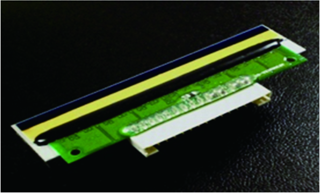
The basic principle is that the resistance of the heating element is formed into a plurality of heating points in a linear configuration on an insulating substrate, and the heating points are selectively energized and heated according to the printed information. When the dielectric coating encounters these components, in a very short time the temperature will rise, and the dielectric coating will undergo a chemical reaction, showing color, thus forming the desired text [4].
III.SYSTEM HARDWARE DESIGN
A.THE OVERALL STRUCTURE OF THE SYSTEM
The overall structure of the FPGA-based TPH control system is shown in Fig. 2. The ARM processor is the main control core and sends data to the FPGA through the External Interface Module (EIM) bus. The EIM bus is a parallel data bus interface and is mainly used to perform data with peripheral memory. Transmission asynchronous communication with the peripheral FPGA can be realized through the EIM bus. The EIM module inside the FPGA is the interface sent from the ARM end to control sending and receiving of data; the clock module is used to synchronize the system clock; the fuzzy controller formulates fuzzy control rules, performs fuzzy inference, and adjusts the PID parameters; and the PID control module then the Strobe (STB) strobe signal that controls the heating of the TPH, and then controls the heating time, so that the print temperature of the TPH is stabilized within the rated range.
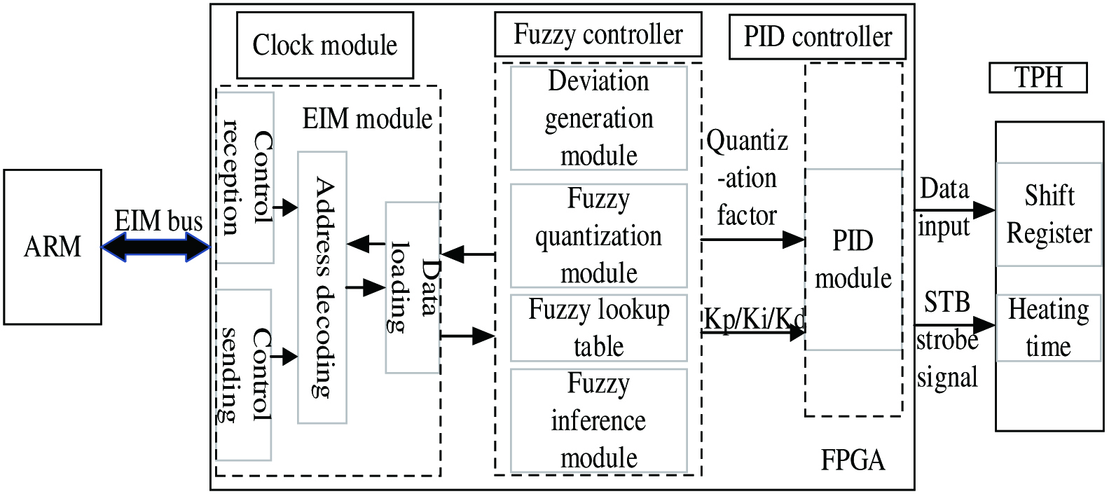 Fig. 2. The overall structure of the system.
The data are distributed to the FPGA through ARM, and the TPH is controlled by the FPGA, which can ensure the real-time performance of the print data. Compared with the direct control of the TPH through ARM, its high-precision printing resolution cannot be met, and the dynamic response time of the print head will also be extended, which does not meet the printing requirements of industrial label printers.
B.FPGA CONTROL TPH HARDWARE CIRCUIT
The main circuit for FPGA heating control of the TPH is shown in Fig. 3. The main control chip uses Xilinx’s Spartan-7 series XC7S6 chip, which has low power consumption, with 6000–10 200 logic units, flexible LUT configurable logic, distributed RAM, or shift register. It is connected with the high-speed CMOS device 74HCT245, which is an eight-way transceiver with an in-phase three-state bus and is compatible output in both sending and receiving directions. And it has easy to cascade output enable (OE) input and send/receive input (DIR) for direction control. OE control output can effectively isolate the bus. The print head model is Toshiba G5141F, the number of heating element points is 1248 points, the dot density is 11.8 points/mm, the printing width is 105.7 mm, the STB1 and STB2 control 1248-point strobe signal, and DATA_IN1-5 controls each point of the print head data input.
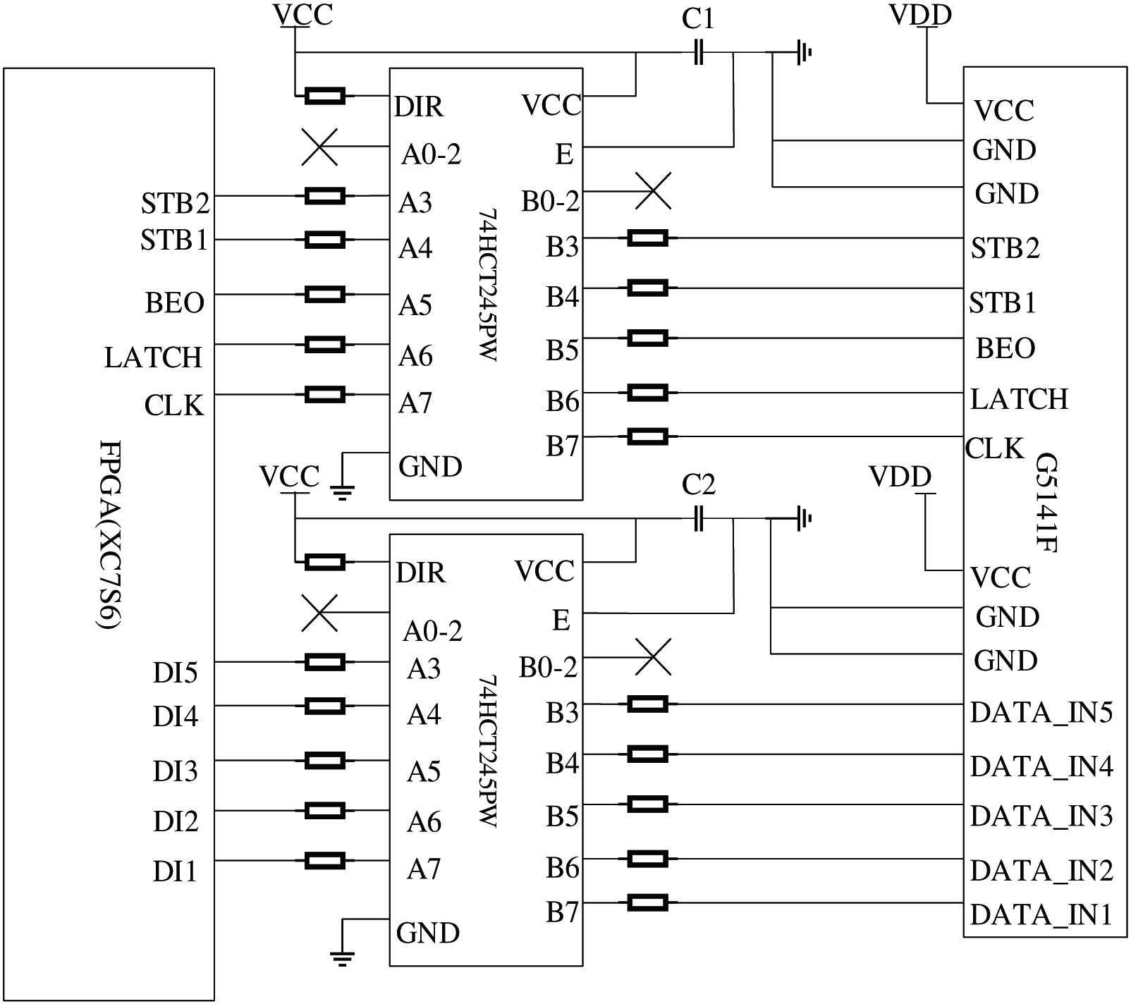 Fig. 3. Print head control circuit diagram.
The working principle of print head heating is as follows. First, there is a shift register inside the TPH, which can store 1248 bits of data. Under the control of the clock signal, the data are shifted into the shift register bit by bit. When all the data in a row are shifted in, latch is the lock save the signal, latch the data, and then start the heating, strobe is the strobe signal, and low is the strobe time for opening the print data. At this time, the heating logic is controlled according to the input data_in data is 1 or 0. Then, the data to be printed is generated.
IV.INTELLIGENT MATHEMATICAL MODEL OF TPH TEMPERATURE CONTROL SYSTEM
By referring to the TPH datasheet, the print head temperature has the following relationship with the thermistor:
where is the thermistor; is the resistance at room temperature 25°C, 30 kΩ; B is a constant, the range is 3970 ± 80; and T is the temperature required when the print head is heated.Therefore, combined with the change rule of the TPH and the thermistor, the temperature change curve of the TPH is shown in Fig. 4. From the perspective of its curve shape, the curve is similar to the “S” shape [5].
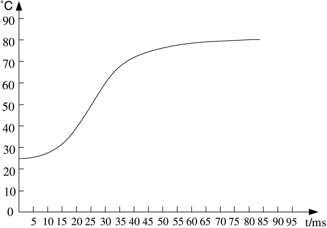 Fig. 4. TPH temperature fitting curve.
It can be judged that the mathematical model of the TPH temperature control system can be approximated by the combination of the first-order inertial link and the delay link. The expression is as follows:
The values of K, T, and τ can be calculated by the following formula:
where is the stable value of the system step response, is the input value, and and are the selected two moments. Thus, we can get K = 0.7, T = 60, and τ = 5.Therefore, the temperature control system model of the TPH is
V.DESIGN OF FUZZY PID CONTROLLER
A.PARAMETER DESIGN OF CONVENTIONAL PID CONTROLLER
The conventional PID controller has a clear structure, convenient parameter adjustment, and strong robustness. At this stage, PID controller parameter tuning methods are mainly theoretical calculation tuning and engineering tuning. Engineering tuning methods include Ziegler–Nichols tuning method, critical ratio method, and attenuation curve method [6].
In this paper, the Ziegler–Nichols tuning method is used to calculate the PID parameters of the TPH temperature control system. According to the empirical tuning formula, the PID initial parameters can be obtained as Kp = 20.5, Ki = 0.26, and Kd = 2.5. Then the mathematical simulation model of the system is built in MATLAB. The simulation model is shown in Fig. 5.
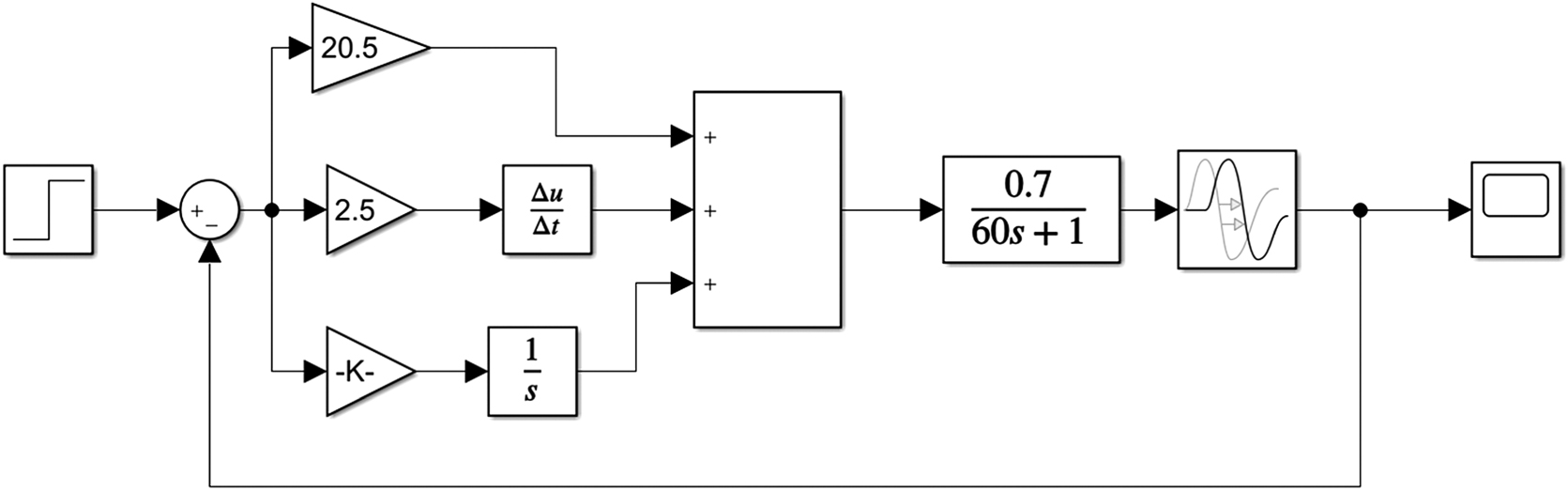 Fig. 5. Conventional PID control simulation model.
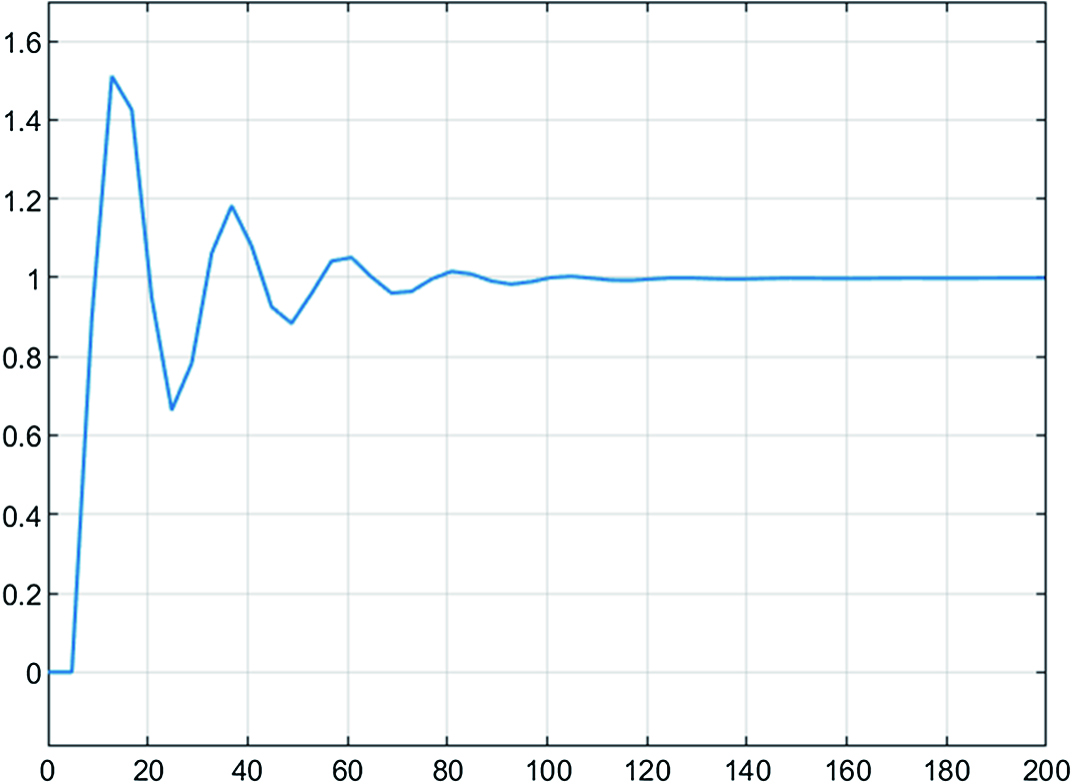
The simulation results are shown in Fig. 6. From the curve, it can be seen that the overshoot is as high as 50%, and the adjustment time is 122 ms. Obviously, this parameter cannot meet the temperature control requirements of the TPH of the industrial label printer. Therefore, a fuzzy controller is introduced to adjust the PID control.
B.DESIGN OF FUZZY PID CONTROLLER
Fuzzy PID control algorithm is an intelligent control algorithm combining fuzzy controller and traditional PID [7]. Fuzzy PID control TPH heating control system is shown in Fig. 7. The establishment of fuzzy PID controller includes four steps: fuzzy processing of input signal, establishment of fuzzy controller rules, fuzzy reasoning, and defuzzification operation of output signal.
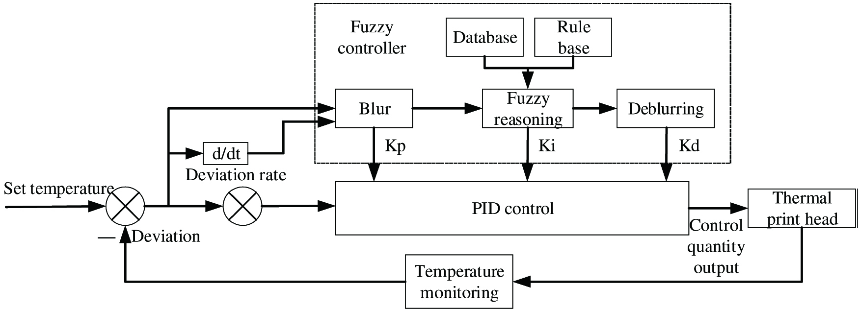 Fig. 7. Fuzzy PID control system.
First, the deviation E and deviation change rate EC of the TPH are two inputs of the fuzzy controller. The deviation amount can be derived from the set input value and the actual value, and then the deviation change rate can be calculated according to the two deviation amounts. The output of the fuzzy controller is the three parameters Kp, Ki, and Kd of PID.
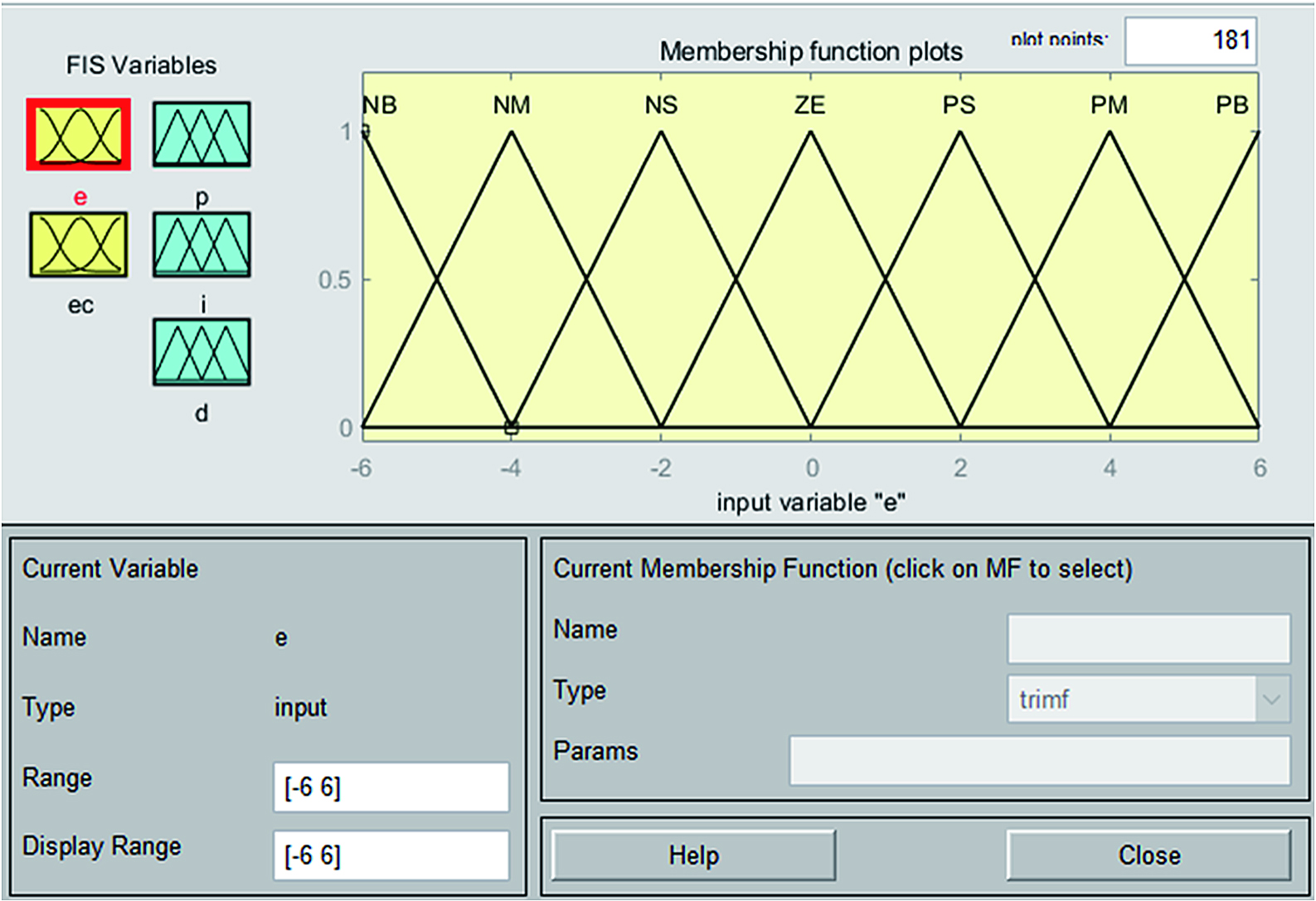
Second, according to the fuzzy control expert experience method, we formulate corresponding fuzzy rules, fuzzify E, EC, Kp, Ki, and Kd, and take the domain of the input quantity [−6, 6]; set the output control quantity Kp according to experience. The domain of Ki and Kd is [−6, 6], [−0.3, 0.3], [−6, 6]; the fuzzy sets of input and output variables are recorded as {NB, NM, NS, ZO, PS, PM, PB}; E and EC use triangular membership function; and Kp, Ki, and Kd are the Gaussian membership functions as shown in Fig. 8.
Then, 49 control rules are established to perform real-time detection and calculation on the output signal of the control system to obtain a fuzzy set of output. For example: “If the temperature of the print head is much lower than the set value, and the temperature rises faster, the heating is faster, that is, the duty cycle of the control signal is increased.” The relationship between the control rule table is “if E is NB and EC is PS, then Kp is PS, Ki is NS, Kd is NS.” Afterward, new conclusions are inferred from the known fuzzy rules through the Mamdani fuzzy inference method. The fuzzy control rules corresponding to Kp, Ki, and Kd are shown in Tables I–III.
TABLE I. Kp fuzzy control rules.
| Kp | EC | |||||||
|---|---|---|---|---|---|---|---|---|
| E | NB | NM | NS | ZO | PS | PM | PB | |
| NB | PB | PB | PM | PM | PS | PM | PB | |
| NM | PB | PB | PM | PS | PS | ZO | NS | |
| NS | PM | PM | PM | PS | ZO | NS | NM | |
| ZO | PM | PM | PS | ZO | NS | NM | NM | |
| PS | PS | PS | ZO | NS | NS | NM | NM | |
| PM | PS | ZO | NS | NM | NM | NM | NB | |
| PB | ZO | ZO | NM | NM | NM | NB | NB | |
TABLE II Ki fuzzy control rules.
| Ki | EC | |||||||
|---|---|---|---|---|---|---|---|---|
| E | NB | NM | NS | ZO | PS | PM | PB | |
| NB | NB | NB | NM | NM | NS | ZO | ZO | |
| NM | NB | NB | NM | NS | NS | ZO | ZO | |
| NS | NB | NM | NS | NS | ZO | PS | PS | |
| ZO | NM | NM | NS | ZO | PS | PM | PM | |
| PS | NM | NS | ZO | PS | PS | PM | PB | |
| PM | ZO | ZO | PS | PS | PM | PB | PB | |
| PB | ZO | ZO | PS | PM | PM | PB | PB | |
TABLE III. Kd fuzzy control rules.
| Kd | EC | |||||||
|---|---|---|---|---|---|---|---|---|
| E | NB | NM | NS | ZO | PS | PM | PB | |
| NB | PS | NS | NB | NB | NB | NM | PS | |
| NM | PS | NS | NB | NM | NM | NS | ZO | |
| NS | ZO | NS | NM | NM | NS | NS | ZO | |
| ZO | ZO | NS | NS | NS | NS | NS | ZO | |
| PS | ZO | ZO | ZO | ZO | ZO | ZO | ZO | |
| PM | PB | NS | PS | PS | PS | PS | PB | |
| PB | PB | PM | PM | PM | PS | PS | PB | |
Finally, deblurring the fuzzy value. The function of defuzzification is to convert the fuzzy quantity into an accurate quantity. It is to clarify the fuzzy control quantity obtained through fuzzy inference and transform it into an accurate quantity that can be used in the controlled system. Through precise scale conversion. It becomes the actual control amount. The conversion from blur to sharpness can use the center of gravity method, the weighted average method, the maximum degree of membership method, etc.
The method used in this paper is the center of gravity method, which calculates the weighted average of each element in the fuzzy output and its corresponding membership degree and transforms it into a control variable acting on the control object by a proportional factor. Theoretically, the center of gravity of continuous points within the range should be calculated [8], and the calculation formula is [9]
But it actually calculates the center of gravity of all sampling points in the output range [10], which is equivalent to discretizing the above formula [11]. In this way, the amount of calculation can be saved, namely,
where is the exact value of the fuzzy variable.Similarly, we can draw [12]
The design of fuzzy PID controller is carried out in MATLAB [12-13], and the TPH control system model is built by Simulink for algorithm simulation and verification. The simulation model is shown in Fig. 9.
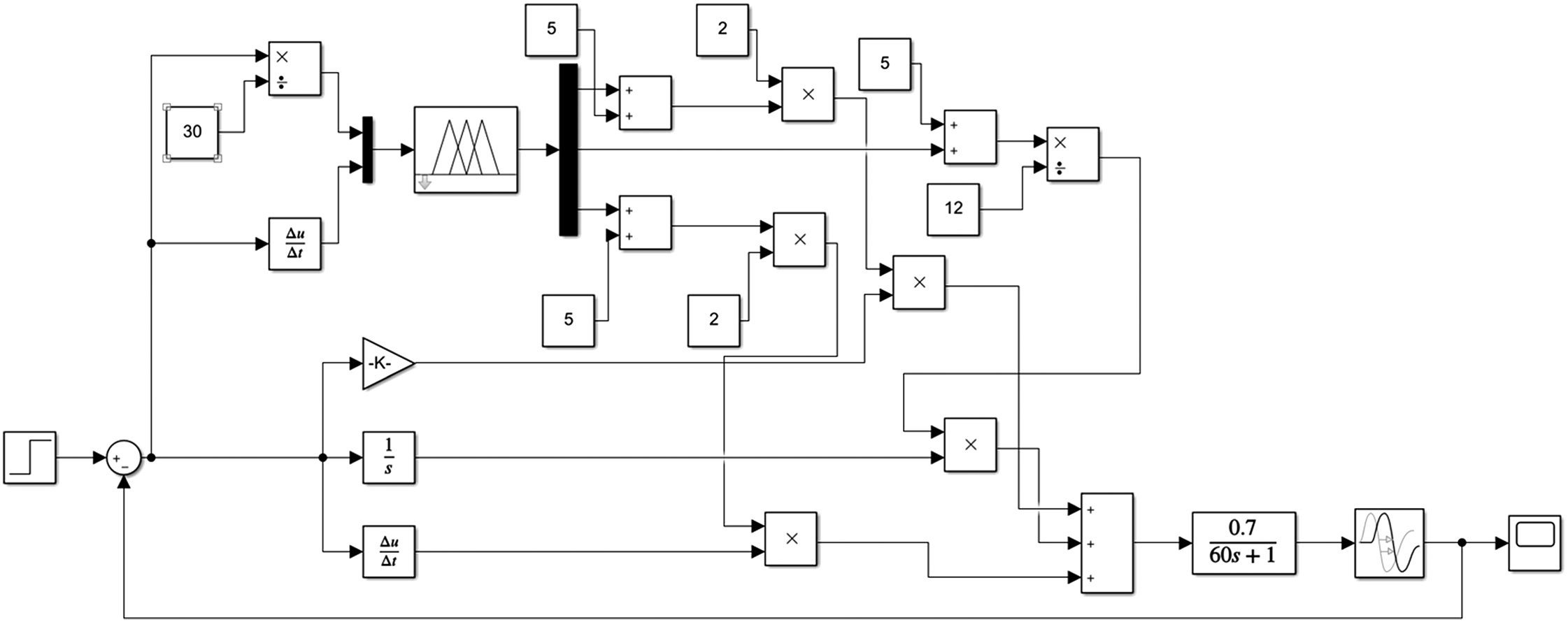 Fig. 9. Fuzzy PID control simulation model.
The simulation results are shown in Fig. 10. From the curve, it can be seen that the fuzzy PID control algorithm can allow the TPH to have a better response speed and reach a stable value faster.
 Fig. 10. Fuzzy PID control simulation diagram.
Analyzing the simulation results of Figs. 6 and 10, the results are shown in Table IV.
TABLE IV. Simulation result analysis.
| Way to control | Adjustment time (ms) | Overshoot (%) | System stability |
|---|---|---|---|
| Traditional PID control | 122 | 50 | Bad |
| Fuzzy PID control | 86 | 23 | Better |
From the above conclusions, it can be seen that the overshoot of fuzzy PID control is small, the control is more sensitive, the speed of stabilization is faster, and the control effect is more ideal. Therefore, the fuzzy PID control algorithm applied to the TPH has a better performance improvement.
VI.TEST IMPLEMENTATION OF FUZZY PID CONTROLLER FPGA
Two methods can be used to implement fuzzy PID control in FPGA [14]: one is to directly implement the fuzzy PID algorithm through hardware. This method is complex in design and consumes too much hardware resources [15]. The other is to use MATLAB simulation design to obtain the fuzzy rule control table [16], and then the fuzzy PID control is realized through the table lookup method. In order to save hardware resources, this paper uses the second method to achieve. Therefore, the control system is mainly composed of a deviation generation module, a fuzzy quantization module, a fuzzy lookup table, a fuzzy inference module, and a PID module, and it completes the corresponding functions in the form of pipeline.
A.DEVIATION GENERATION MODULE
The formula of the incremental PID control algorithm [17] is .
Incremental PID control algorithm only needs to calculate the increment, there is no accumulation item, and the output control increment is only related to the last three sampling values [18]. When there is a calculation error or the accuracy is not enough, its influence on the calculation of the control quantity is small. Therefore, this paper uses incremental PID control algorithm to calculate the deviation.
The error generation module generates three adjacent deviation values e(k), e(k − 1), and e(k − 2). It is obtained by subtracting the actual output value from the temperature setting value of the TPH, e is the deviation value, ec is the deviation rate, and e0, e1, and e2 correspond to the above deviation values, respectively.
B.FUZZY QUANTIZATION MODULE
The TPH temperature deviation and the deviation amount is an accurate amount, and the fuzzy inference system needs to fuzzify the accurate amount, and it determines the fuzzy set to which the input value belongs according to the corresponding membership function, that is, divide the basic analects into a number of interval segments, the accuracy of the input. The value corresponds to the corresponding interval value. For example, in this paper, the basic domain of TPH temperature is divided into [−30, 30], E and EC are discretized, The deviation of E is quantized, EC is the rate of variation of deviation after being quantified. The quantization factor is five, and the corresponding elementary domain of the fuzzy set is [−6, 6]. There are 13 discrete values, and the input deviations E and EC are divided into 13 segments: [−30, −28), [−28, −23), [−23, −18), [−18, −13), [−13, −8), [−8, −3], [−3, 2), [2, 7), [7, 12), [12, 17), [17, 22), [22, 27), and [27, 30], the corresponding quantitative domain value is [−6, −5, −4, −3, −2, −1, 0, 1, 2, 3, 4, 5, 6]. The division here is just to generate the following address codes to facilitate the design and use of subsequent memory.
C.FUZZY LOOKUP TABLE
Encode the divided discourse domain to generate the address of the lookup table. The discrete value of fuzzy quantization module is divided into 13 segments, using four-bit binary coding, E and EC form an eight-bit address, and the first four bits of the address are E, address. The last four digits are EC, the quantified E and EC, the fuzzy input domain is discrete, and the number is limited. The model of fuzzy logic function established in MATLAB is input to the fuzzy for different E and EC combinations. The corresponding Kp, Ki, and Kd are found in the inference module. Table V shows the quantized value corresponding to the input.
TABLE V. The quantized value corresponding to the input.
| Interval value | [−30, −28) | [−28, −23) | [−23, −18) | [−18, −13) | [−13, −8) | [−8, −3) | [−3, 2) | [2, 7) | [7, 12) | [12, 17) | [17, 22) | [22, 27) | [27, 30] |
|---|---|---|---|---|---|---|---|---|---|---|---|---|---|
| E/EC | −6 | −5 | −4 | −3 | −2 | −1 | 0 | 1 | 2 | 3 | 4 | 5 | 6 |
| Quantized value | 0000 | 0001 | 0010 | 0011 | 0100 | 0101 | 0110 | 0111 | 1000 | 1001 | 1010 | 1011 | 1100 |
D.FUZZY INFERENCE MODULE
The fuzzy inference module determines the appropriate output value according to the input value. The inference process is controlled by fuzzy rules. In this paper, the data obtained by the inference are stored in the ROM in the FPGA. When it is to be used, the PID value module is output by the lookup table method to control the PID module.
VII.WAVEFORM SIMULATION TEST
Using XILINX’s Vivado for programming and simulation, the programming uses Verilog HDL language, through the program debugging to get the ideal simulation effect. Fig. 11 shows the fuzzy PID control simulation diagram of each module of the TPH.
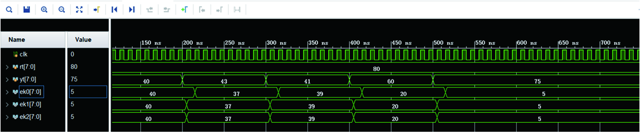 Fig. 11. Simulation diagram of deviation generation module.
The simulation diagram of the deviation generation module is shown in Fig. 11, where rt is the system setting value and yt is the actual output value of the system. Observing the waveform shows that the module meets the design requirements.
According to the division of the universe of discourse segments and the corresponding quantized values shown in Table V, when the input deviation E is 30, the corresponding domain of discourse is [27, 30], and the corresponding quantization value is 1100; it is 25, the corresponding domain segment is [22, 27], the corresponding quantization value is 1011, and the combined output address is 11001011. From the simulation diagram shown in Fig. 12, it can be seen that the program design is correct, and the correct fuzzy quantization is achieved and combined address function.
 Fig. 12. Fuzzy lookup table simulation.
From the simulation result of the fuzzy inference module shown in Fig. 13, it can be seen that the appropriate output can be output in time for the input E and EC. When the input E is 30 and EC is 25, the three parameters of Kp, Ki, and Kd are 60, 15, and 10, respectively. The corresponding quantized value and address are also correct, which meets the design requirements of the fuzzy controller.
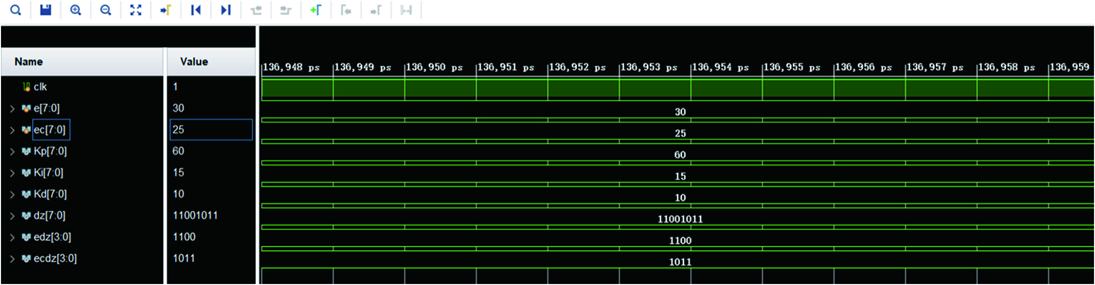 Fig. 13. Simulation diagram of fuzzy inference module.
From the simulation results shown in Fig. 14, it can be seen that the output uout follows the five input changes of Ki, Kp, Kd, rt, and yt. According to the previous analysis, the output results are analyzed and verified, and the output is controlled according to the incremental PID. The algorithm formula can be calculated as
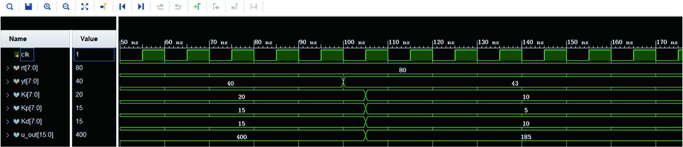 Fig. 14. The PID module simulation diagram.
The above-mentioned calculated data are consistent with the FPGA simulation result, so the realization procedure of the designed fuzzy PID control algorithm is correct.
VIII.CONCLUSION
The TPH is the most critical part of the printer. Various websites and literatures have very few control designs for the TPH, especially the FPGA to control the TPH, but in real society, the control of the TPH must maintain a high degree of real time and high-precision control. Therefore, this paper introduces the research of FPGA-based TPH control system in detail in combination with the actual industrial label printer. By using the fuzzy PID control algorithm, the temperature control of the TPH is effectively improved, which has a high reference value.