I.INTRODUCTION
A.BACKGROUND AND MOTIVATION
Standing is one of the most serious and important activities of daily living because of the possible lack of strength and stability in the elderly [1,2]. Typically, in bad cases, an incapacitated elderly person may not be able to stand up and subsequently become limited to wheelchair living or bedridden [3]. Furthermore, when the elderly fall into this lifestyle, the lack of exercise and consequent decline in physical fitness becomes more promoted [4]. Therefore, there is a need for an assistive robot to help the use of residual muscle strength during voluntary movements in order to maintain the patient’s muscle strength.
To achieve this goal, the assistive robot must be designed to accept some degree of variability in the patient’s body movements, as human movement does not always conform to the established reference pathway [5]. However, many existing standing assistance robots assist the patient to stand up on a predesigned trajectory [6–9]. During the standing motion, these robots interfered with the patient’s body movements and were adjusted to conform to the reference pathway. Such external interventions would prevent the patient from using his or her own strength in the process of standing up, which would result in a decrease in the patient’s muscle strength.
B.PROBLEMS IN OUR PREVIOUS RESEARCH AND OBJECTIVE OF THIS PAPER
In order to address this problem, we defined the “safety tolerance” as the range in which a person can continuously perform standing motions from the standpoint of physical balance and muscle strength [10]. Furthermore, we developed a standing assistance robot as Fig. 1 which allowed the patient’s voluntary movements as long as the patient’s posture was within the safety tolerance. Using this idea, our robot could use the patient’s physical strength as much as possible.
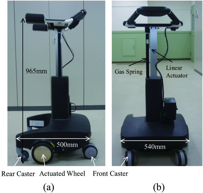 Fig. 1. Our assistive walker (a) side view and (b) front view.
This idea works if the patient’s motion is essentially the same, though with errors, as the robot’s expected motion. However, when the patient does not perform the movements assumed by the robot, the robot may assist extraordinarily or, conversely, the robot’s assistance may be delayed. For example, if the patient falls, the robot should assist the patient immediately, but with our previous algorithm [11], the robot prioritizes the patient’s spontaneity until it gets out of the safety tolerance. Furthermore, as shown in Fig. 2, if the patient raises her hips earlier than the robot expects and she exceeds the safety tolerance, the robot will force her to return to the original motion. These problems occur because the patient’s movements are considered only in terms of the safety tolerance. In order to provide safe and smooth standing movement assistance in keeping with the patient’s intention, the robot needs to judge the risk of the movement deviating from the target trajectory according to the type of movement intended by the patient, for example, tilting the upper body, lifting the upper body, etc. Furthermore, even if the patient’s motion is within the stability margin, the robot should provide the necessary assistance depending on whether the patient’s motion is going to deviate or not.
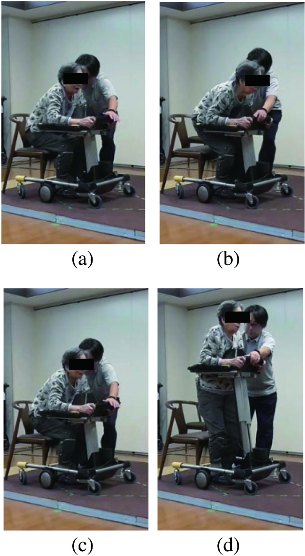 Fig. 2. Typical failure. She tried to stand up early in (b) and was forced back by the robot in (c).
Therefore, the objective of this study is to extend the concept of the safety tolerance and propose a concept called the “safety motion tolerance” that defines the range of movements which ensure the safety of the patient. Furthermore, this paper proposes a method of assisting the patient to stand up while using their physical strength, by allowing the robot to make movements based on the patient’s will, as long as they are within the “safety motion tolerance.”
II.SAFETY TOLERANCE
A.CONDITIONS FOR A SUCCESSFUL STANDING MOVEMENT
In terms of body mechanics, the safety standing motion must meet two conditions. The first condition is stability condition. The patient should be able to maintain body balance during standing motion. We define this condition as: the center of gravity (COG) position is within range of the patient’s feet, while maintaining body balance when standing.
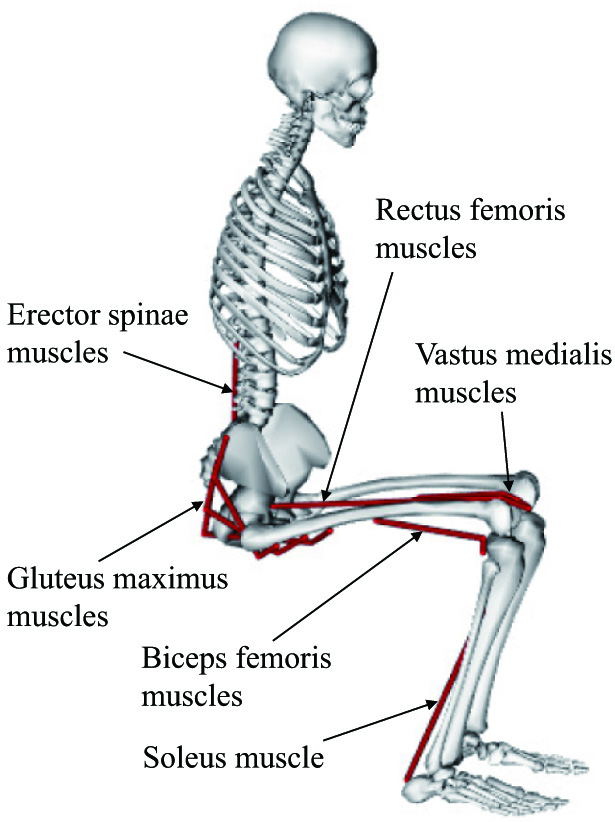
The second condition is muscle condition. The patient should be able to control his or her body movements when standing. In general, the positional relationship between muscle and bones changes depending on a subject’s posture [12], so the output force generated by a muscle changes with posture. In other words, in an unsuitable posture, it is not possible to generate enough upward output force to advance the standing motion. In this study, this muscle condition is defined as the required output force of the muscle shown in Fig. 3 should not exceed the maximum output of the muscle during standing up.
B.INVESTIGATION OF SAFETY TOLERANCE FOR EACH FACTOR MOVEMENT
In our previous studies [10], we have examined the acceptable range that satisfies these conditions through computer simulation using OpenSim [13], a human motion dynamics simulator package. However, our previous studies discussed whether mechanically random postures satisfy the stability and muscle conditions and did not discuss the characteristics of the safety tolerance for each of the several movements that make up the standing movement. Furthermore, since standing movements are symmetrical, we considered standing movements as motions in the sagittal plane and did not consider left-right motion stabilization. In practice, human motion always includes a trajectory error of about 5% [14], even in healthy people, and the safety tolerance of left-right motion should also be considered.
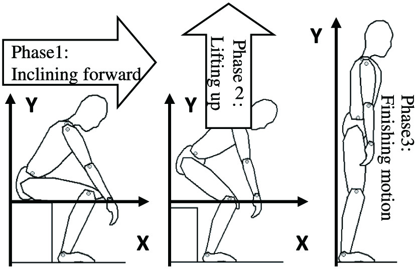
In general, a standing movement consists of three phases, as shown in Fig. 4. Therefore, in this paper, using a three-dimensional human model, we generate motions for each phase by adding a variation to the basic standing movement. Furthermore, we investigate the safety tolerance by checking whether these motions satisfied the stability and muscle conditions using computer simulation.
1)SIMULATION SETUP
In this simulation, as shown in Fig. 5, 3DGait-Model 2392 [13] is used as the human body model and the body parameters are changed to match a typical Japanese elderly person [15]. The standing movements are based on references recommended by physical therapist [16], as shown in Fig. 6a. The angular changes in each joint of the patient during this movement are shown in Fig. 6b. In Fig. 6b, the y-axis shows the angular values of the pelvis and trunk and the knees and ankles, and the x-axis shows the movement pattern [10], which is the ratio of the standing movement, as shown in (1).
where ts is the time required for completion of the standing operation and t is the present time. Fig. 5. Human model and its coordination. (a) side view and (b) front view.
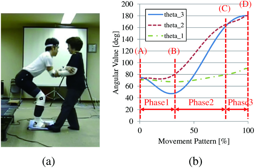 Fig. 6. Standing motion recommended by a nursing specialist. (a) standing motion and (b) angular value.
In this computer simulation, the variation of the movements was increased by adding fluctuations to the basic movements by the physical therapist, and it is verified whether the human model could satisfy the stability and muscular conditions in each movement. Each phase is therefore subjected to a computer simulation with a variation of 30 [deg] width in the reference posture (postures (b)–(d)) at the end of each phase. Note that since posture (a) is the start posture and he sits on his chair, thus, no variations were set in posture (a).
C.SIMULATION RESULTS AND DISCUSSION
The simulation results are shown in Fig. 7. Figure 7 shows the position where the subject’s COG, P, can satisfy the stability and muscular conditions. In other words, the gray-filled area in Fig. 7 indicates the safety tolerance, which extends before and after the standing trajectory recommended by the physical therapist. If the patient adopts a posture in which the P-point is within the safety tolerance, the patient’s postural stability is maintained and guaranteed to be able to continue standing with his or her own muscle strength.
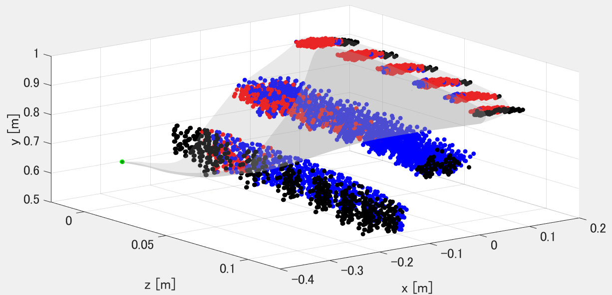 Fig. 7. Investigated safety tolerance. Each point represents the position of the P-point when the human is in a posture. The red dots represent postures that satisfy both stability and muscle conditions. Blue dots represent postures in which the stability condition was satisfied, but the muscle condition was not. Black dots indicate postures in which both the stability and muscle conditions were not satisfied.
From Fig. 6, although the standing movement is a sagittal movement, the posture is tilted from the center to the z-direction, indicating that the safety tolerance is reduced. Figure 8 is therefore shown in order to verify in the sagittal plane how the safety tolerance changes as the posture inclines in the z-direction.
 Fig. 8. Investigated safety tolerance on sagittal plane. Each point represents the position of the P-point when the human is in a posture. The meaning of each color is the same as shown in Fig. 7. The green line is the trajectory of the P-point when the subject stands with a recommended way by the nursing specialist, and the stability margin range is within the red-filled area. (a) Z=0[m], (b) Z=0.02[m], (c) Z=0.04[m], (d) Z=0.06[m], (e) Z=0.08[m], and (f) Z=0.1[m].
From Fig. 8, we can see that the safety tolerance decreases as the body’s inclination in the z-direction increases. Furthermore, at the same body inclination in the z-direction, the safety tolerance of the first phase is the smallest and that of the third phase is the largest. In particular, in Fig. 8e there is no safety tolerance in the first phase and in Fig. 8f there is no safety tolerance in the first and second phases. This means that if the patient takes a posture where the Z-coordinate of the P-point is more than 0.08 [m], the buttocks cannot be lifted from the seat of the chair. It also means that in a posture with a Z-coordinate of 0.1 [m] or more, the patient cannot lift his/her upper body.
The above simulation results show that the safety tolerance for standing movements has the following characteristics.
- •The safety tolerance when the patient lifts his/her buttocks up from the chair is smaller than in the other phases and is also susceptible to being smaller by inclination of the body in the z-direction. This means that in the movement of leaning forward and lifting the buttocks from the chair, the allowed motion variation is small and the patient is required to perform the movement in the correct trajectory.
- •The safety tolerance in the movement of trunk extension is the largest compared to the other phases and is not affected by body inclination in the z-direction. This therefore means that the patient’s motion fluctuation is more easily acceptable in the third phase of the standing movement.
- •The safety tolerance in the second phase is larger than in the first phase and smaller than in the third phase. In other words, the motion fluctuation allowed to the patient is greater than in phase 1 and less than in phase 3.
From the above, we investigate that in the standing movement, the patient requires the most accurate movement when lifting the buttocks, and that the error allowed in the movement increases as the body is lifted.
III.SAFETY “MOTION” TOLERANCE AND STANDING ASSISTANCE BASED ON IT
A.POSTURE ESTIMATION USING LOW-COST SENSOR
In our previous research, we have developed robotic walkers with an assisted standing function [10–12,17,18]. A latest prototype [19] is shown in Fig. 1. The robotic walker has a motorized walker and a standing support manipulator with an armrest to move upward so that the user can be lifted. The wheel actuators on the powered walker are used to stabilize the user when a standing support manipulator lifts the user.
To estimate the posture of the patient, we used an inexpensive two-dimensional laser range finder. As shown in Fig. 9a, our robot equips the laser range finder. The range of movement of the body during the standing motion is limited, and the main problem is the body movement in the x- and y-directions as shown in Fig. 9a. Therefore, if the laser range finder is installed at an appropriate position, it is possible to measure the patient’s posture even with an inexpensive 2D laser range finder as shown in Fig. 9b.
 Fig. 9. Its equipped 2D laser range finder. (a) Position of LRF and (b) measured data.
In this study, the human body was approximated as a linked model as shown in Fig. 10a. From the point data measured by the laser range finder as shown in Fig. 9b, the end points of each link are estimated as shown in Fig. 10b. The estimation algorithm was developed in our previous work [17]. The position of the COG of each link ((xi, yi), i is 3, 4, and 5.) was estimated from the end points of each link. In this study, the COG position of the link was assumed to be at the midpoint of the link. From the position of the COG of each link and the weight of each link, the position of the COG of the patient can be expressed by (2) as shown in Fig. 10c and d:
where mi is mass of each link. The mass of each link, which is one of a physical parameter, was obtained from a previous study of the elderly Japanese [8]. Fig. 10. Real-time estimation of the center of the gravity of the patient. (a) Linkage model, (b) estimation of each joint, (c) estimated COG, and (d) estimated COG and its safety tolerance.
As described above, our robot can estimate the COG of a patient’s body on sagittal plane and his/her safety tolerance in real time as shown in Fig. 10d.
On the other hand, it is difficult to directly measure the left-right movement of the upper body with inexpensive sensors equipped on the robot. By the way, when the user’s upper body is inclined, the hand on the side of the inclination tends to support more force. Therefore, this study used force sensors installed in the armrests of the robot to estimate the user’s upper body inclination by measuring the difference in the force applied by the user between the left and right sides of the body.
Figure 11 shows the sensors installed in the armrest of the robot. The user rests their elbows on the armrests when standing up and is assisted by the upward force from the robot. From the force data applied by the user to the left and right armrests, the robot can estimate the position of the COG of the armrests as in (3). l is the distance between the left and right sensors.
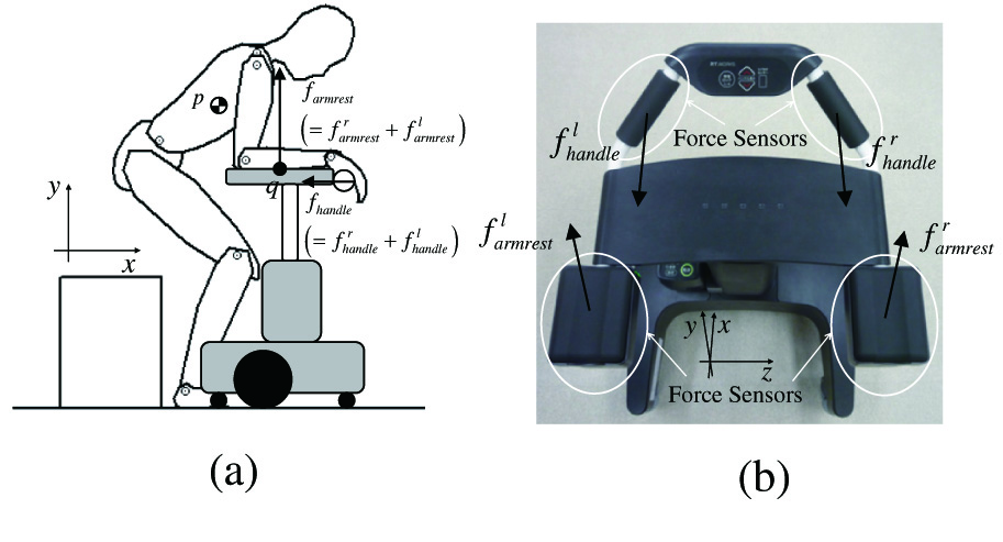 Fig. 11. Force sensors equipped on our robot. (a) Direction of measuring force and (b) top of our robot.
As a preliminary experiment, we investigated the relationship between the actual body COG and the forces applied to the left and right armrests of the robot when five healthy subjects perform standing movements. Furthermore, as the relationship between the force applied to the armrest and the position of the user’s center of gravity may differ depending on the type of movement, we performed measurements in the first, second, and third phases of the standing motion, respectively.
Figure 12 shows the results of preliminary experiments. The experimental results show that there is a correlation between the force applied to the armrest and the body COG. We therefore decided to estimate the body COG using the proportional correlation between the COG of its user and applied force on the left and right armrests of the robot, as in (4). The correlation was found in all phases of the first, second, and third phases of the standing motion, but the proportionality coefficients were different, so the proportionality coefficients ki (i = 1, 2, 3) in (4) were set for each motion:
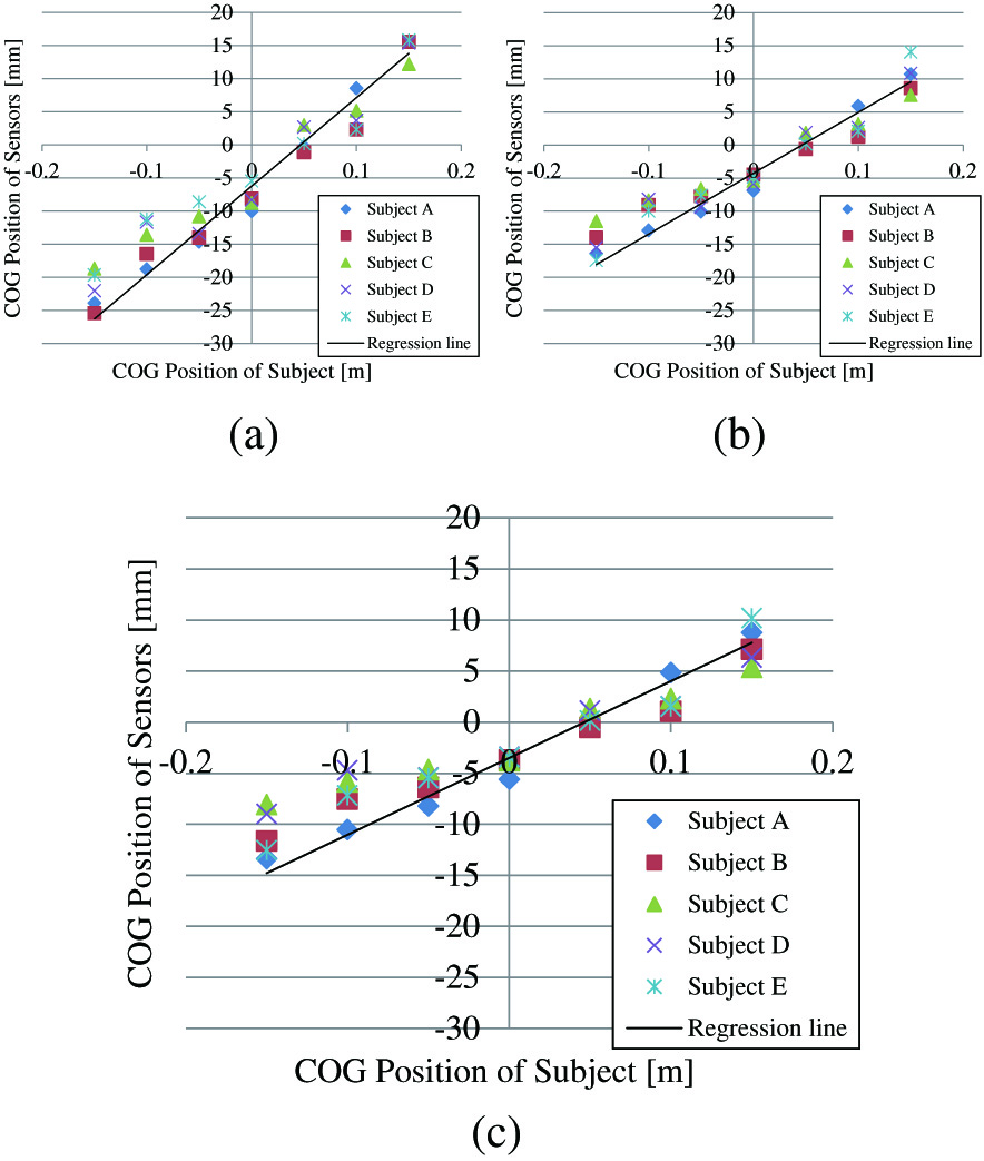 Fig. 12. Relationship between the left-right difference in force applied to the armrest and the position of the center of gravity (P-point). (a) Phase 1, (b) Phase 2, and (c) Phase 3.
B.PROPOSAL OF SAFETY MOTION TOLERANCE
When the COG is within the safety tolerance, the patient’s body stability is maintained and the caregiver is able to continue standing up with his or her own muscle strength.
In our previous study [6], we proposed a method to assist the patient to stand up by simply changing the assistance force control depending on whether the patient is within the safety tolerance or not, giving priority to the patient’s voluntary movements. However, there are problems with this assistance method, as discussed in section 1. From them, it is important not only to consider the posture of the patient but also to evaluate whether or not the movements the patient is performing will be within the safety tolerance when deciding on standing assistance scheme.
Therefore, we propose an estimation method for the stability of a patient’s movement. In order to determine whether a patient’s voluntary movement is safe, it is necessary to estimate the movements that are likely to be made within the safety tolerance, such as motion A in Fig. 13, and the movements that are likely to deviate from the safety tolerance, such as motion B, from the stage when the patient is still operating within the safety tolerance.
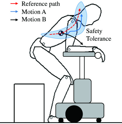 Fig. 13. Reference path and the patient’s motion in safety tolerance.
The trajectory that the body’s COG takes when the patient performs the standing motion recommended by the physical therapist can be expressed by (5). is matrix data listed by the movement pattern . These data are derived kinematically in advance from body parameters such as height [8]. The standing motion recommended by physical therapists is a sagittal plane motion, so the left-right position of the subject performing the standing motion is expressed as (6):
If the patient performs a movement that is different from the trajectory of the reference standing motion at the movement pattern τ as shown in Figs. 14a and 15a, the velocity vector of the actual patient’s body , the velocity vector by the reference standing way , and the velocity vector of the difference between them is expressed as (7):
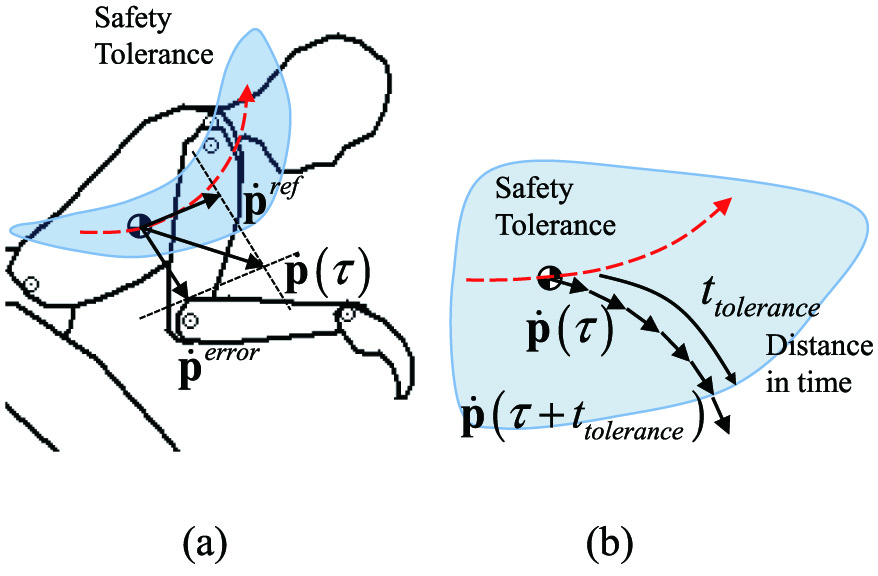 Fig. 14. Safety tolerance and safety “motion” tolerance. (a) The error motion and (b) estimation of distance to the outside of tolerance.
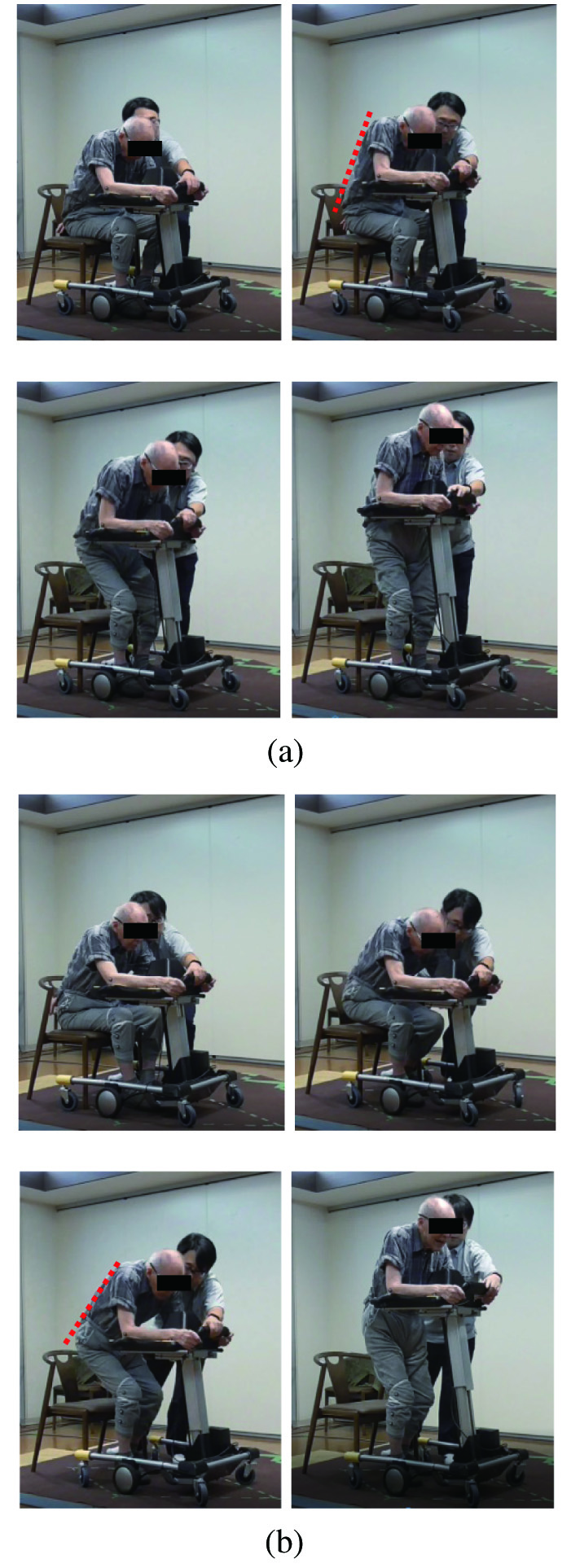 Fig. 15. Standing motion (subject A). For safety reasons, the physiotherapist waited next to the subject. During the experiment, he did not assist the subject. (a) Case 1 (fix reference pathway, without our proposed scheme); (b) case 2 (considering tolerance posture, with our proposed scheme).
If the patient continues the motion at the movement pattern τ, the position of the COG at t can be expressed by (8) as shown in Figs. 14b and 15b:
Using (5), we can calculate the time when the COG deviates from the safety tolerance by real-time computer simulation.
From the above, assuming that the patient continues to act at movement pattern τ, the time when the patient can stay within the safety tolerance is (9) as follows:
where represents the distance in time to the wall in the safety tolerance of the patient’s movement. In other words, it is an indicator of the safety of the patient’s movements. If is larger value, the patient’s motion will be done within the safety tolerance and its risk is low. On the other hand, is smaller value, the patient’s motion has high risk. In this paper, we call as safety motion tolerance.IV.ASSISTANCE CONTROL USING SAFETY MOTION TOLERANCE
A.PROPOSAL OF ASSISTANCE CONTROL ALGORITHM
In this section, we propose an algorithm that combines the assistance scheme for standing up with those that use the patient’s residual physical ability and those that provide quick supporting for risky movements of the patient. Specifically, when the patient’s motion is within the safety tolerance, our robot gives priority to the patient’s voluntary movement and uses assistance measures that use the patient’s own muscle strength by damping-based control[18]. On the other hand, if there is a risk of the patient’s movement deviating from the safety tolerance, even if the patient’s posture is within the safety tolerance at that point, our robot gives priority to safety and uses assistance scheme to maintain the patient’s posture safely by position-based control.
If the patient’s posture falls outside the safety tolerance, our robot will operate using positional control in order to prioritize the maintenance of the patient’s posture for safety reasons. As shown in Fig. 11a, our robot has a standing support manipulator (y-direction) and motorized walker (x-direction), but our robot does not have a function to guide the posture in the z-direction. So if the patient falls out of the posture in the left or right direction, our robot will not allow free movement of the patient and assist based on fixed reference value for safety reasons by position-based control.
The following is a description of the specific proposal methodology on sagittal plane. As shown in Fig. 11a, the patient puts his or her weight on the armrest at the top of our assistance robot and grasps the handle to get assistance force from our robot in the x- and y-directions. Our robot has force sensors on its handle and armrest as shown in Fig. 11b. Using these equipped sensors, our robot measures applied force to armrest (, y-direction) and handle (, x-direction) by the patient during standing up.
Our robot assists the patient at q point in Fig. 11a. Our robot has control references for each actuator as detailed in (10), which realize the designed standing motion as (5). is velocity reference vector of q point, is the motion reference for a powered walker, and is for a standing assistance manipulator:
Our robot uses the force sensor equipped on its top for switching condition between the position control and the damping control as (11):
where is the updated reference value that our robot actually uses for delivering standing assistance. is the actual position of the powered walker and the standing assistance manipulator of our robot. Bj and Kj (j=sm: standing manipulator, pw: powered walker) in (11) are constants used to coordinate the ratio between the damping and position controls. and are the forces the patient applies to the assistance system before he or she stands.B.SWITCHING SCHEME BETWEEN DAMPING CONTROL AND POSITION CONTROL
In order to apply the damping control only when the patient’s motion fulfills safety “motion” tolerance discussed in previous paragraph, the coefficient Bj that validates the damping control mode is calculated as (12). Bj will be larger value if the safety motion tolerance has enough time distance and as the result, our robot allows the patient to move according to his or her intention:
By contrast, the position control is always useful because it helps the patient maintain a stable posture during motion. Therefore, we set the coefficient Kj which validates the position control mode, to be constant.
The discussion in Section II shows that the first phase of the standing movement, that is, lifting the buttocks from the seat surface, requires a small and precise postural error to be allowed. On the other hand, in the third phase of the standing movement, that is, the movement to extend the trunk, a large motion error oscillation is allowed. Considering these conditions, the parameters in phases 1 to 3 were experimentally determined as shown in Table I.
| Phase 1 | Phase 2 | Phase 3 | |
|---|---|---|---|
| bj | 0.2 | 0.5 | 0.8 |
| Kj | 0.7 | 0.5 | 0.4 |
V.EXPERIMENT
A.EXPERIMENTAL SETUP
We implemented our proposed idea to the prototype (Fig. 1a) and conducted a practical experiment with it. To confirm the efficiency of our standing assistance scheme, we tested two cases:
- •Case 1: Using only position control, without our proposed idea (fix reference path).
- •Case 2: Using our proposed idea (reference path with posture motion tolerance).
We used eight subjects and each subject attempted all two cases, two times each. Subjects were elderly whose care levels [15] are 1 or 2 as shown in Table II. For each of these individual subjects, safety motion tolerance was designed and standing assistance movements based on this were performed on the prototype robot. Furthermore, we measure the surface electromyograms on several body segments, motion data (using motion capture system), and ground reaction force (using force plate) during a standing motion.
| Subject | Height [cm] | Weight [cm] | Age | Gender | Care level |
|---|---|---|---|---|---|
| A | 160 | 57.2 | 83 | M | 1 |
| B | 157 | 54.9 | 81 | F | 2 |
| C | 150 | 38.5 | 78 | F | 1 |
| D | 159 | 52.9 | 85 | M | 1 |
| E | 149 | 52.1 | 82 | F | 2 |
| F | 163 | 58.0 | 83 | M | 2 |
| G | 151 | 42.7 | 87 | F | 2 |
| H | 150 | 39.9 | 84 | F | 1 |
B.EXPERIMENTAL RESULTS
Figs. 16 and 17 show the standing process of subject A and B. In each case, subject A and B succeeded to stand with our assistive robot. No subject failed to stand as Fig. 2 with our proposed assistance. In this experiment, all subjects inclined their upper body at the begging of standing process with our proposed scheme. This motion moves COG to the sole of the foot, and it is important for its user to stand up by own physical strength. Thus, we can assume that using our proposed assistance scheme, the subject stood with his/her intended movement.
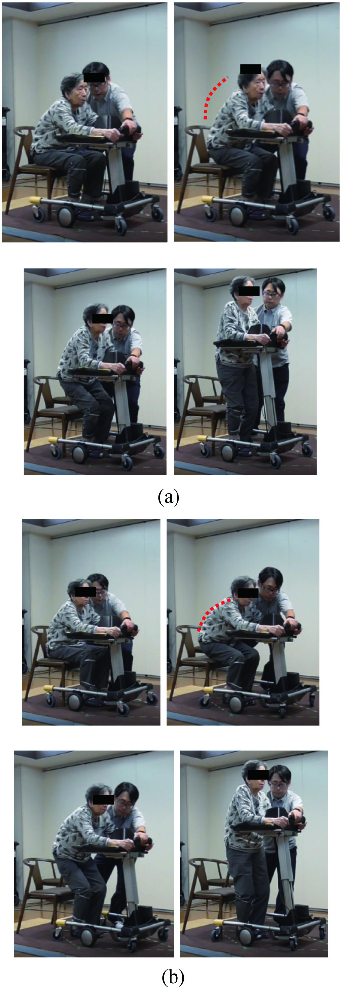 Fig. 16. Standing motion (Subject B). She is round-backed. For safety reasons, the physiotherapist waited next to the subject. (a) Case1 (Fix reference pathway, without our proposed scheme). (b) Case2 (considering tolerance posture, with our proposed scheme).
 Fig. 17. The ratio between the activity of each muscle during standing motion at case 2 and case 1. If the value is larger than 1, case 2 uses larger physical strength comparing with case 1.
Figure 17 is muscle activity of rectus femoris muscle, gluteus maximus muscle, and erector spine muscle. Figure 17 shows how large the muscle activity is at case 2 if the muscle activity at case 1 is 1. From Fig. 17, we can verify that with proposed scheme, all muscles works harder than without proposed scheme. This means proposed assistance control uses its user’s physical strength effectivity.
Figure 18 shows physical activity of rectus femoris muscle during standing process at subject A. From these results, the subject A used his own physical strength to lift off his buttocks from chair to finish his standing process. Lifting off phase requires his COG on the sole of the foot; thus, we can verify that allowing intended motion is effective for using the remaining of physical strength of its user.
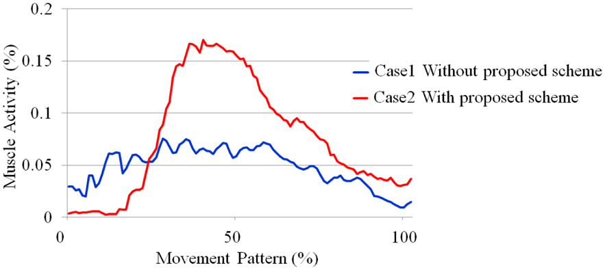 Fig. 18. Activity of rectus femoris muscle during standing process (subject A).
Figure 19 shows the ratio of muscle activity during standing process between case 2 (with proposed scheme) and case 1 (without proposed scheme). From Fig. 19, our assistive robot used remaining physical strength of subject A, C, D, E, F, G, and H with our proposed control algorithm. On the other hand, subject B did not use own physical strength because she did not incline her upper body during standing motion as shown in Fig. 16. In other word, she failed to stand with her own intention and her motion exceeds the safety tolerance. However, even if she failed, our robot succeeded to assist stand-up motion safely using our proposed assistance scheme. She finished her stand-up motion with our robot, not as shown in Fig. 2.
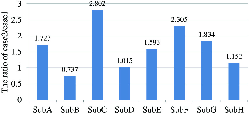 Fig. 19. The ratio between the activity of rectus femoris muscle at case 2 and case 1. If the value is larger than case 1, case 2 uses larger physical strength comparing with case 1.
According to these results, our robot succeeds to provide assistance to subjects while also allowing them to use their own physical strength. Furthermore, even in an unsuitable movement, our robot succeeded to assist the patients and finish their standing motion safely.
VI.CONCLUSION
This paper proposed a novel standing assistance scheme, which allowed patients to maximize the use of their physical strength. To realize this, we proposed posture estimation scheme with low-cost sensors and voluntary movement evaluating method from the view point of safety “motion” tolerance. Our novel assistance control scheme selected more appropriate control method from position and damping control using safety “motion” tolerance as an index. Furthermore, our proposed control scheme switched between both control methods appropriately according to the risk of each phase of the standing movement. We conducted practical experiments to confirm the efficiency of the proposed idea implemented in our prototype of a robotic standing assistance device.