I.INTRODUCTION
Developing a control system for an active exoskeleton with the use of operator’s electromyogram (EMG) as the setting signal has its own distinctive features. Thus, the creation of exoskeleton device with an EMG-based control system that takes into account the interaction of humans and exoskeleton design elements becomes one of the most actual tasks of modern robotics. Unlike bilateral systems, the operator is strictly linked to the slave system of the exoskeleton, which imposes restrictions on movement speed and acceleration [1]. The control algorithms for such type of exoskeleton device should include consideration of tremor and fatigue to ensure safety in control.
Robotics is the central topic of the latest physical artificial intelligence. Modern methods of controlling complex mechatronic systems require a special approach to calculate the parameters of the control system, which would take into account the current psychophysiological state of the operator. The issues of interaction between human-machine systems and the operator are currently being discussed. In particular, researchers are trying to synergistically combine knowledge from different fields of science to achieve the concept of effective human-machine interaction. For example, the authors of paper [2] discussed the application of physical artificial intelligence that could link computing, biology, chemistry, and material science. Paper [2] discussed some of the aspects, such as computer science algorithm, biological control, and of course, mechanical design.
The relevance of the current research is related to the need of improving the quality of control in the human-machine system, due to the adaptation of the control system to the psychophysiological characteristics of the certain operator. Determining the critical parameters of the electromyogram readings during training and performing technological operations will allow one to develop effective algorithms for adapting the control system to the influence of external and internal factors on control [3]. The control system needs adjusting parameters to take into account the appearance of a new operator or adjust these parameters in the conditions of monotonous work and the appearance of signs of fatigue. For example, the authors of paper [4] described modern evaluation methods for muscle fatigue based on the surface EMG data analysis in statics and dynamics. The authors showed that continuous monitoring of local muscle fatigue when performing certain physical work is possible by measuring the myoelectric activity of individual muscles using surface electromyography methods. The practical application of such techniques in relation to an exoskeleton device, the control system of which is based on the use of information about muscle biopotentials, is the possibility of creating an algorithm for configuring the exoskeleton control system for a specific user and for a specific task type.
In previous works, researchers have proved that muscle fatigue is expressed a decrease in frequency and an increase in the amplitude of the electromyogram signal [5]–[7]. Thus, it is important to take into account the individual characteristics of each skeletal muscle involved in control. These features are expressed in the variation of geometry [8], force and velocity of contraction dependences [9], conductivity of the skin [10,11], the age of the operator [12], the level of its muscle tone [13]–[15], and so on. Therefore, when developing an exoskeleton control system, it is reasonable to create special databases for different groups of operators with similar characteristics. Based on the obtained characteristics, one can develop a set of values for each group, which will serve as a reference when calibrating the control system.
II.THE EXPERIMENTAL STAND SPECIFICATION
Earlier in our work [16,17], we performed mathematical modeling of the interaction between the exoskeleton and the operator. These theoretical studies have shown the importance of the operation mode (speed mode and compensation of external forces mode when holding an object).
This paper presents the creation of a working model of the elbow exoskeleton device, and it presents the results of experimental studies conducted in the Laboratory of Robotics and Mechatronics of the Institute for Problems in Mechanics of the Russian Academy of Sciences. The technical scheme of the designed stand is shown in Fig. 1.
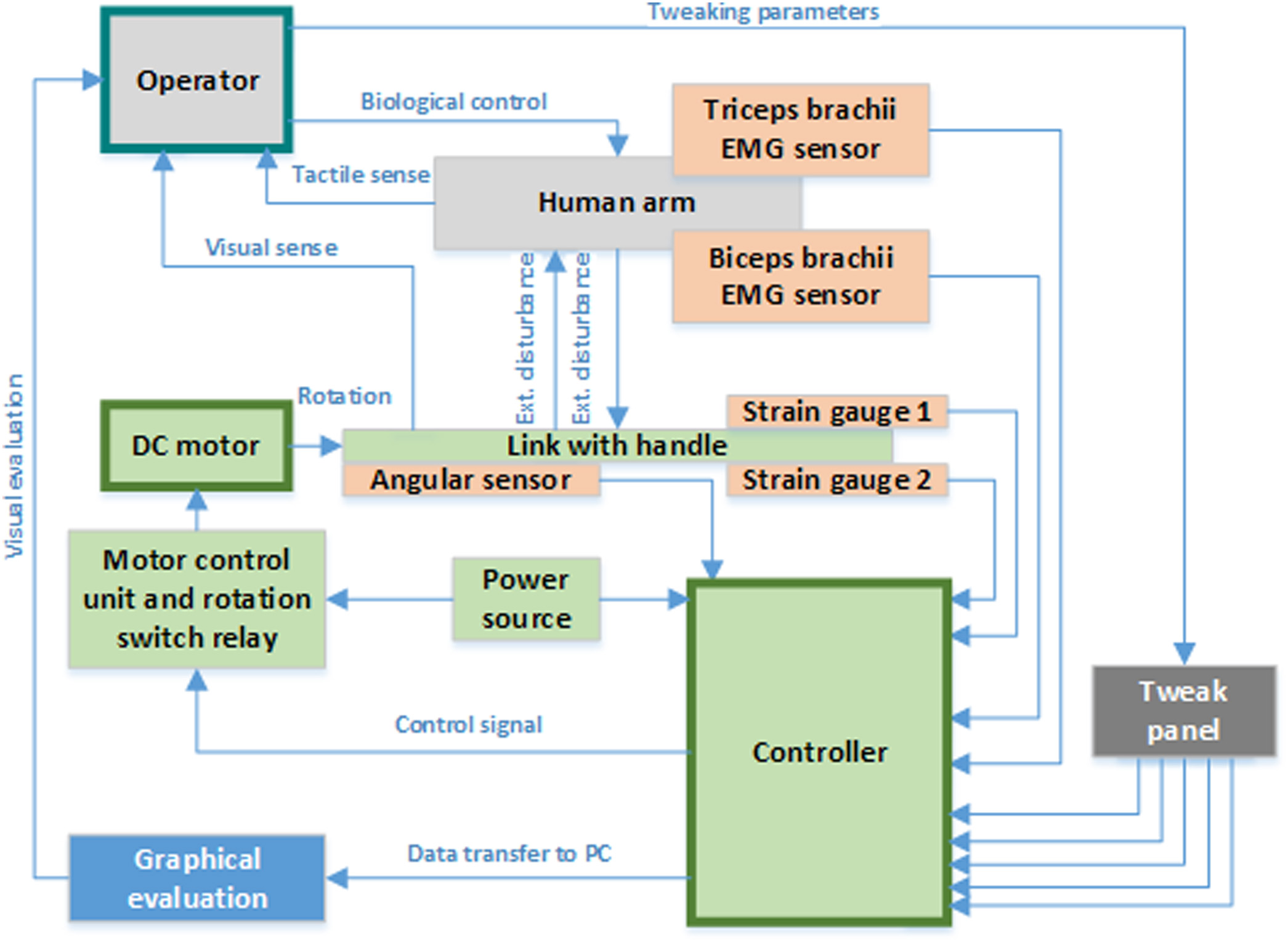 Fig. 1. The technical scheme of the system.
The experimental stand contains a control unit that receives information about the current position of the exoskeleton elements in space and the state of activity of the operator’s muscle groups. The exoskeleton link, driven by a direct current (DC) motor, is equipped with power sensors that measure the reaction forces between the structural element of the exoskeleton and the operator’s arm. The operator uses visual and tactile channels to evaluate the motion.
In our research, we used two DC motors. One of the DC motors was equipped with a reversible gearbox so that the operator could feel the reaction forces while holding the load in isometric operation. Another DC motor was equipped with a worm gear to simulate motion blocking when implementing an algorithm for determining the maximum force parameter from various operators.
To evaluate the reaction forces, we used two strain gauges integrated into the exoskeleton handle with a maximum payload of 500 N and an HX711 ADC unit with a resolution of 24 bits and 80 Hz measurement frequency (Figs. 2–4). To tune control parameters, a control panel with a set of variable resistors was implemented, which allows correcting the transmitted values according to the proposed algorithms.
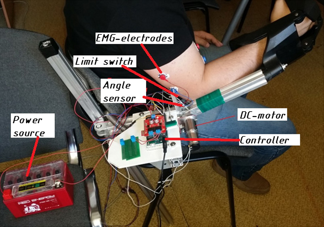 Fig. 2. General view of the experimental stand at the final stage of development (with operator).
 Fig. 3. Power electronics onboard.
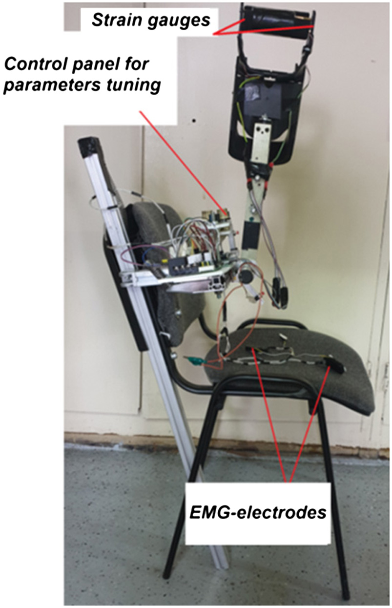 Fig. 4. General view of the experimental stand at the final stage of development (without operator).
To obtain data on the muscle activity, Myoware Muscle Sensors AT-04-001 were used. Their applicability for obtaining an electromyogram of muscles was discussed in paper [18]. In this work, we used the raw signal from these sensors to improve performance and apply our own software filter with dynamic adjustment of filtration parameters. For processing the obtained data and form the control signal via pulse-width modulator (PWM), we used a controller based on the Atmega2560 RISC processor with a clock frequency of 16 MHz and a 10-bit ADC.
III.THE EXPERIMENTAL RESULTS
On the basis of the laboratory, we conducted several groups of experimental studies. A group of three test subjects was created. The first experiment was to find out the difference in EMG behavior among three subjects in simple motion. The total electromyogram data in this experiment were the readings of the potential difference on the biceps brachii and the triceps brachii .
Within the control program, the obtained data of the triceps brachii were taken with a negative sign to determine the direction of movement of the exoskeleton link from the resulting sign of the total data .Fig. 5 shows the results of an experiment on bending and unbending the arm at the elbow with a weight of 3 kg for each of the subjects. In this experiment, the behavior of an electromyogram without filtering was evaluated.
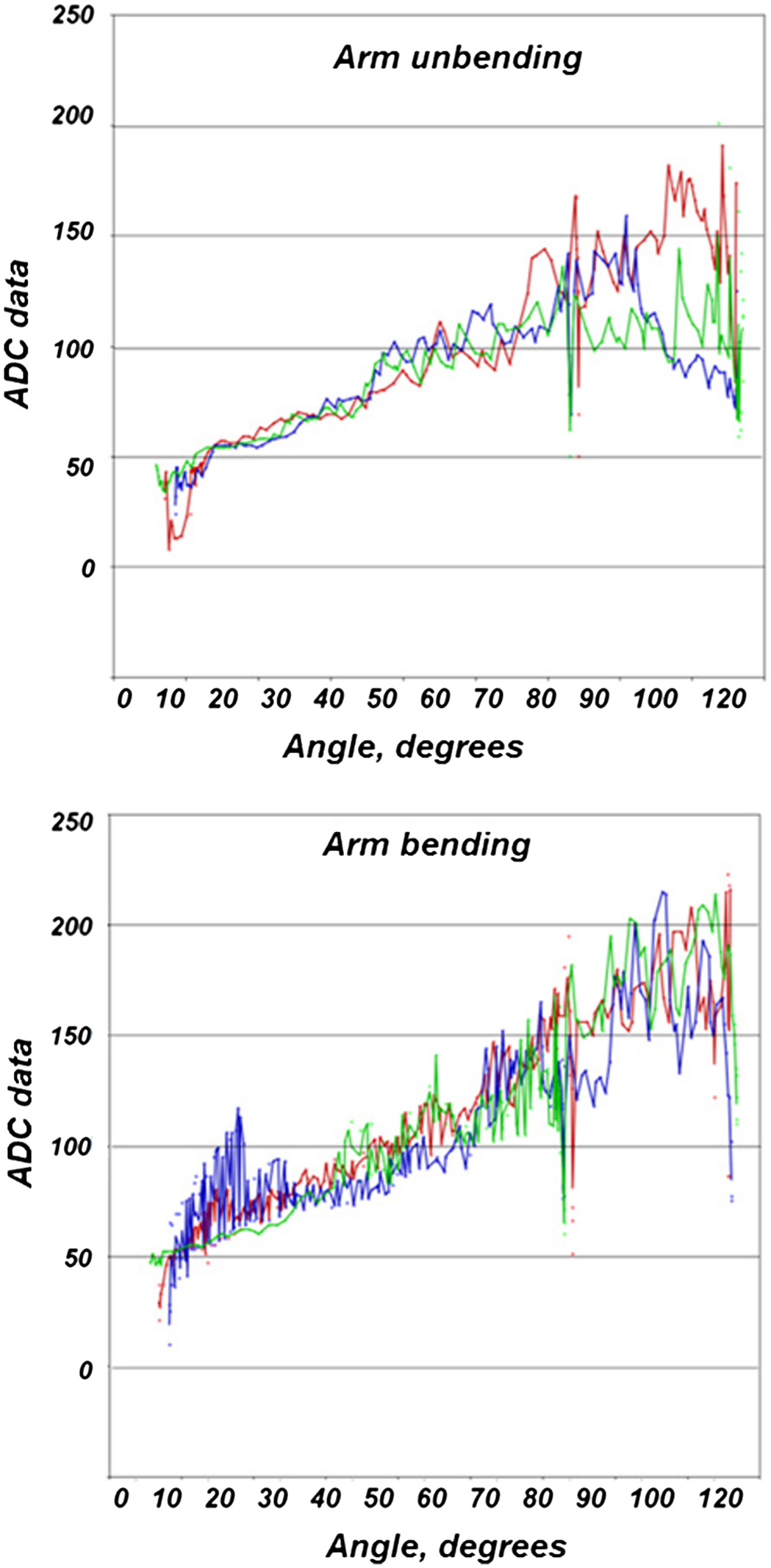 Fig. 5. Raw total EMG data of the biceps and triceps brachii.
Here, one can see a tendency of increasing the EMG amplitude with an increase in the angle in the elbow joint.
This effect can be explained that the arm compensates the gravity of the payload with the most active biceps brachii. As shown by further experiments, to obtain a negative value of the parameter , which means that when activating the reverse rotating of the exoskeleton’s motor, it is necessary to take into account the position of the arm in space and the individual characteristics of the muscles used.
From this, we can conclude that value of the parameter must be corrected
where variables and are the functions that depend on the maximum effort that a given muscle can develop. Maximum forces for each muscle were obtained in the experiment using strain gauges. In the control system, these parameters are used as settings for the sensitivity of sensors to changes in the electromyogram amplitude. Table I shows the results of numerical adjustment of parameters and for each test subject in the group when setting the movement at a uniform speed.TABLE I. The results of the settings.
| Parameter | Parameter | |
|---|---|---|
| Subject 1 | 0.861 | 1.074 |
| Subject 2 | 0.911 | 1.268 |
| Subject 3 | 0.927 | 0.983 |
| Average in the group | 0.899 | 1.108 |
Changes in the amplitude of the graphs obtained in this experiment indicate the presence of noise that needs to be filtered. Therefore, the next group of experiments was used to configure the noise filter [19] for the parameter entering the control system. For this experiment, the moving average algorithm was selected. This algorithm allows filtering out low frequencies. Implementing this filter in the control system requires setting two parameters – the time constant and the filtration coefficient. The value of the filtered parameter will depend on the parameter value on the current and subsequent sensor polling cycle:
where the parameter N = [0…1] is the filtration coefficient. Increasing the value of this parameter leads to the return of the influence of noise on the received signal; however, as it was shown by experimental studies, a high value of this parameter reduces the sensitivity of the control system. If the filtration coefficient is high, it is difficult for the operator to make a sudden movement or to change the direction of movement. The time constant specifies the time interval during which averaging will occur. An increase in the time constant leads to smoother changes in the parameter , but it introduces a noticeable delay in control. In the course of experiments, it was found that increasing the time constant parameter is suitable for slow movements characteristic of the exoskeleton load holding mode or for improving positioning accuracy. Sudden movements that are typical, for example, for fast technological operations, require reducing this coefficient.
As part of the experiment, the subjects were given the task to bend and unbend the arm at the elbow in an exoskeleton while holding loads of different weights and at the same time observe a constant speed. The speed constancy was controlled in the developed program. During the experiment, the settings for the filter time constant T and the filter coefficient n were changed. When the flexion-extension speed was constant for five approaches, the current parameters were recorded in the database. In this case, the angular range of 10°, set aside for acceleration and deceleration near the extreme positions defined by limit switches, was not taken into account. Table II shows the final values of the parameters after the experiment.
TABLE II. The results of the settings.
| Fast movement (1 s to overcome 100°) | Slow movement (4 s to overcome 100°) | |||
|---|---|---|---|---|
| Parameter (kg) | (ms) | (ms) | ||
| Subject 1 | ||||
| 1 | 2 | 0.05 | 4 | 0.1 |
| 3 | 2 | 0.05 | 5 | 0.1 |
| 5 | 3 | 0.04 | 5 | 0.08 |
| Subject 2 | ||||
| 1 | 2 | 0.05 | 4 | 0.1 |
| 3 | 2 | 0.05 | 5 | 0.1 |
| 5 | 2 | 0.05 | 5 | 0.09 |
| Subject 3 | ||||
| 1 | 2 | 0.06 | 5 | 0.1 |
| 3 | 3 | 0.05 | 5 | 0.09 |
| 5 | 3 | 0.05 | 5 | 0.08 |
| Average in the group | 2 | 0.05 | 5 | 0.09 |
From this table, one can see that increasing the weight of the load leads to the need of increasing the value of the filter time constant to obtain a constant speed of movement of the exoskeleton link. This can be explained by the fact that the increased load on the biceps led to the involvement of more motor units per unit of time, which led to an amplification of the EMG signal and an increase in the amplitude of noise, which had to be filtered by increasing the value of the time constant of the filter.
When performing the movement in slow mode, the load on the biceps lasted longer, so the effect of fatigue is visible here, expressed a decrease in frequency and an increase in the amplitude of the useful signal. The next group of studies was aimed at identifying the value of the dead zone for the assigned biopotential. Experiments have shown that even in the state of rest and noise filtering, the value of will be different from zero, and because this value is used to form the motor speed, constant small deviations of the rotor from the current position are possible in the state of rest. Therefore, the speed calculation algorithm has been adjusted to take into account the dead zone parameter, which is configured individually for each operator.
The final experiments were used to check the values of the control system parameters calibrated according to the found standards for the fourth untrained test subject.
A load of 5 kg was placed on the handle of the test stand, and the task of moving at a constant speed was set. Here are screenshots of the program written in “Processing” that represent the interface to obtain data from experimental stand (Figs. 6 and 7).
 Fig. 6. The result of an experiment with a fourth subject with a calibrated control system when implementing slow movements.
 Fig. 7. The result of an experiment with a fourth subject with a calibrated control system when implementing fast movements.
The results of the tests showed the efficiency of the proposed algorithms for calibrating and configuring the parameters of the exoskeleton control system.
From the results of the experiment (Figs. 5 and 6), it can be seen that when implementing slow movements, the value of parameter (biceps brachii data channel) and the value of parameter (triceps brachii data channel) are numerically less than one.
These parameters are the coefficients before the actual values of the filtered data readings obtained from the sensors located at the biceps and triceps brachii skin areas of the operator’s shoulder, respectively.
Thus, if we consider the slow movements of the operator’s limbs (in the experiment, the operator’s forearm was estimated to overcome the range of 100° in 4 s when rotating in the elbow), the uniformity of speed throughout the entire section was achieved with a decrease in these coefficients. Fig. 8 schematically shows the situation that leads to a change in this coefficient on the example of channel B (biceps brachii data channel).
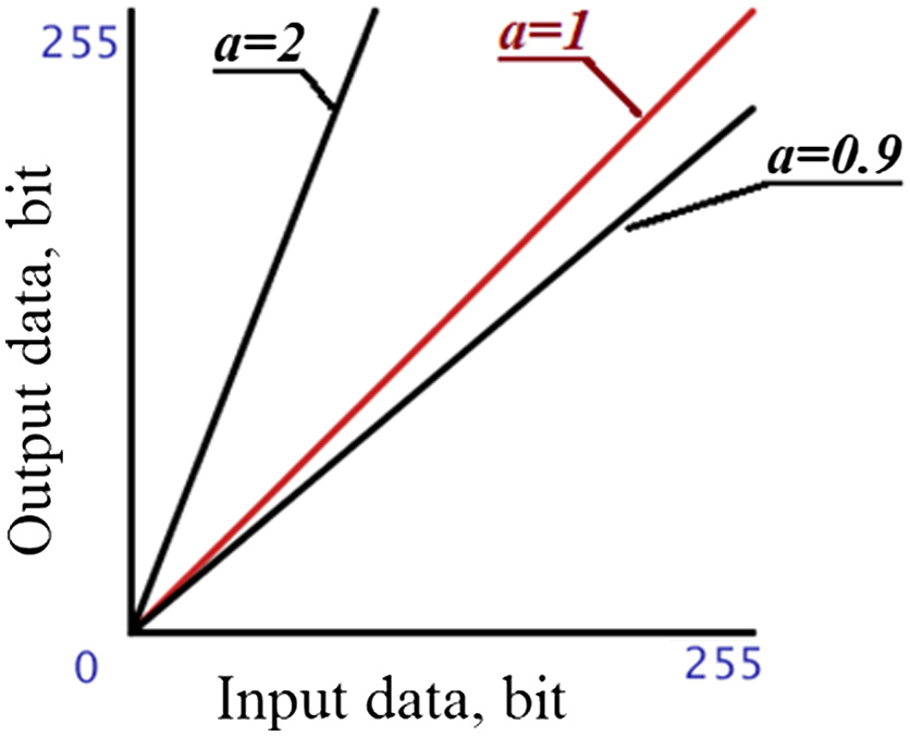 Fig 8. Typical linear functional dependence.
In this case, when performing slow movements, this setting will reduce the influence of noise on the formation of the output data value (e.g., speed). However, to realize high speeds of movement, this coefficient must be increased so that the output value changes faster than the input value.
Within the project, a technique is proposed that can combine the advantages of setting the conversion coefficient of the control value for low and high speeds. To do this, it is proposed to change the control value nonlinearly. That is, in this case, (2) is transformed into the following:
where and are the corrected values of the obtained EMG data from the biceps brachii and triceps brachii sensors of the operator, respectively. At the same time, a nonlinear law of correction of the control parameter was implemented for the control system using the Bezier curves technique. This technique was chosen because it allows one to build a continuous curve inside a given area with control points (see Fig. 8) and at the same time allows one to dynamically changing the shape of the curve. Therefore, for example, if one takes as a basis the construction of a cubic curve described by a system of equations in parametric form:then, if the coordinates , , , are known, one can create the necessary curve by specifying only the coordinates of two points – T1[] and T2[]. Fig. 9 shows examples of the functional dependencies of the adjusted parameter on the parameter formed on the basis of data obtained from the EMG sensor. Fig. 9. Examples of setting the sensitivity of the control system.
In Fig. 9, one can see that by changing the coordinates of points T1[] and T2[], one can adjust the sensitivity of the output value (in this case, this is the adjusted parameter of the operator’s muscle biopotential data) to the change in the input value (in this case, this is the data obtained directly during the measurement and passed the primary filtering).
Thus, applying the proposed technique of sensitivity adjustment to the exoskeleton control system, it is possible to implement various modes of its operation. For example, if the coordinates of the point T1 and the coordinates of the point T2 are numerically identical, respectively, then the functional dependence of the corrected value on the measured value will set into a linear one (Fig. 9a). Fig. 9b shows that when the biopotential signal changes in the region close to zero, the corrected value changes slowly, which allows getting rid of the influence of noise at weak signals and set more smooth control of the movement of the exoskeleton. In the presence of a high biopotential corresponding to the operator’s desire to increase the speed of movement of the exoskeleton link, the adjusted value changes faster, this allows implementing a fast positioning mode.
In Fig. 9b, one can see the situation that characterizes the slow mode of operation of the exoskeleton. This mode is used when the accuracy of movement is important. This dependence can be divided into three sections. The first section, characterized by a weak signal, is described similarly to the area close to zero from Fig. 9b. In this area, weak noise, interference, and small fluctuations in the biopotential signal are filtered. The second section has a characteristic close to linear, and the last section reduces the influence of random signal fluctuations at high speeds or under smooth muscle tetanus.
As part of the work, it was possible to obtain various data for several operators, on the basis of which reference values of the control system parameters for calibration for a group of operators were obtained. The results of testing the developed algorithm on full-scale stand imitating the exoskeleton arm with the electric drive, located in the elbow joint, and controlled with algorithms based on the dynamics of the EMG envelope of the biceps brachii and triceps brachii of the operator.
IV.CONCLUSION
In the course of experimental studies, the influence of various parameters of the control system on the quality of movement control of the exoskeleton device was shown. The experimental stand and special software were developed to allow flexible configuration of the control system parameters. As part of the work, various data were obtained for several operators, on the basis of which reference values of control system parameters were obtained for calibration. The results of testing the developed algorithm on full-scale stand, simulating the arm exoskeleton with the DC drive, located in the elbow joint and controlling algorithms based on the pattern envelope electromyogram of the biceps brachii and triceps brachii of the operator were presented. The structure and features of the stand developed in the Laboratory of Robotics and Mechatronics of IPMech RAS are shown. A comparative characteristic of the quality of control of the DC drive that is part of an exoskeleton, on which the proposed algorithm for configuring the control system in relation to one operator when changing to another was worked out. The following control quality indicators were evaluated – over regulation (when evaluating the speed), time to set the specified position (when setting the filter coefficients and determining the numeric value of the dead zone parameter), and the accuracy of positioning the control point on the exoskeleton link. The sensitivity adjustment technique within the exoskeleton control system is proposed.