I.INTRODUCTION
Corrosion of structures costs the UK economy approximately 3.5% of its gross domestic product annually [1] and results in £100 billion yearly for repairs and downtime. Automated methods of corrosion detection and timely repair can reduce the economic impact. Reinforced concrete (R/C) is used throughout the civil engineering industry for roads, bridges, high-rise buildings, dams, cooling towers, etc. Global corrosion repair costs for R/C are about 8% of all corrosion costs [2]. It is estimated that this is about £8 billion per annum in the UK alone. The R/C inspection is mostly performed manually by constructing expensive scaffolding or by using ropes to reach a test site. The risk of accidents and falls can be reduced by using robotics to perform the inspection. Mobile robots must first provide access to test sites on large vertical surfaces before the inspection can be performed. Many types of wall-climbing robots have been developed for various tasks. Some survey papers capturing these developments are [3]–[5]. Wall-climbing robot research tries to increase payload capacity, mobility, and adhesion forces and to minimise energy consumption [6,7].
Wall-climbing robots have been developed for nondestructive testing [8], laser cutting for nuclear decommissioning [9], window cleaning [10], maintenance and inspection of vertical structures [11], inspection of petrochemical tanks [12], and wind turbine towers/blades [13].
The technology used by wall-climbing robots to create adhesion forces includes vacuum generating devices that use centrifugal pumps, turbines, and compressed air [14]. A review of electro-adhesion technologies [15] and the problems of adhesion and locomotion of wall-climbing robots are described in [16]. The adhesion methods and materials for bio-inspired climbing robots are described in [17]. Most problems of structural integrity have to do with large steel structures such as petrochemical storage tanks, ship hulls, bridges, monopiles, and wind turbine towers. On these structures, the best adhesion method is obtained by using permanent magnets or electromagnets. Wall-climbing robots using this method are reported in [18,19].
The novel robotic development reported here, SIRCAUR, uses a permanent magnet climbing robot. It adheres to concrete reinforcement bars to reach test sites on vertical structures to detect rebar corrosion and delamination defects with 100% volume coverage. Tests have been performed on a concrete wall with rebars at depths of 30–35 mm from the surface. The design, prototyping, and testing of the robot are illustrated in this paper. The climbing robot was able to climb on concrete structures with rebar density at these depths, and the ground-penetrating radar (GPR) system was able to effectively detect defects.
This paper is the extension of a previously published conference article in [20]. The paper has been extended by including the design of our “flux focusing design toolbox”, built as an application on top of COMSOL Multiphysics to assist the design of permanent magnet adhesion systems for climbing robots. Results of experiments to validate the Toolbox have been included. New experiments have been performed that validate our adhesion system designed for R/C structures. The following sections describe the crawler’s design. Section II describes the design of the adhesion module. Section III describes the prototype and the submodules that comprise the crawler’s payload. Finally, Section IV presents our conclusions.
II.CRAWLER’S DESIGN: THE ADHESION MODULE
To design climbing robots for industrial applications, it is important to consider the operating environment and the task to be carried out [6]. Robots that can climb on nonferrous surfaces tend to employ either suction cups or dynamic vortex adhesion methods which produce a vacuum with fast-spinning impellers. These methods require constant energy supply lines for long inspection times which result in long umbilical cables. To climb on structures constructed from ferrous materials, permanent magnets or electromagnets are preferred as they provide higher adhesion forces. Electromagnets control the adhesion force on demand but again require a constant energy supply to maintain adhesion to a structure. Permanent magnet adhesion is the best method for robots climbing on ferrous structures as the force is constant and can be engineered to be high with magnetic flux focusing techniques, does not need the application of power, and is fail-safe in the event of power failure to the rest of the robot.
SIRCAUR has been designed to use permanent magnets to adhere to reinforcement bars (rebars) buried in concrete and to use GPR to detect rebar corrosion and other concrete defects. The design of the climbing robot has attempted to increase payload capacity, mobility, adhesion safety, and to minimise energy consumption. Permanent magnets are used for the adhesion method for two reasons: (a) The method does not require energy consumption, therefore, avoiding the use of heavy batteries that will increase the payload. (b) In case of a power failure, the crawler will remain attached to the surface providing a safety feature. Our previous research to develop the technology to focus magnetic flux to couple with rebars buried in concrete and develop concrete climbing robots has been reported in [21–25].
The next subsections will explain the design of the crawler based on its adhesion module and payload.
A.THE FLUX FOCUSING APP
To design a robot that uses permanent magnets to adhere to rebars at a distance of 30–40 mm from the magnet system, it was necessary to first develop a design tool that predicts the adhesion force when flux focusing techniques are used with different magnet systems comprising different types of permanent magnets, yokes of different materials, and magnet placement configurations.
This section describes the development of the design tool used to select the best magnet system. Analysis of forces on a climbing robot on a vertical plane is given in [4].
Permanent magnet adhesion climbing robots developed for climbing on concrete structures are discussed in [6]. Engineering of these types of climbing robots remains a difficult trade-off challenge because increasing the payload target requires larger drive motors/gears which, in turn, increases the weight of the robot and requires more adhesion force to remain attached to a surface. Obtaining sufficient adhesion force to safely carry a target payload when the air gap between magnets and rebars is more than 30 mm is the major challenge. A numerical modeling optimization process was carried out to retrofit previously published adhesion mechanisms. To tackle the analysis of this problem, COMSOL Multiphysics was used to model the permanent magnet adhesion system.
Adhesion modules were investigated that used several permanent magnets and flux concentrators or “yokes” in different configurations to optimize the adhesion module to give a maximum adhesion force with a minimum weight of the module.
B.SIMULATION OF ADHESION FORCE UNDER IDEAL CONDITIONS
To ensure the reliability of modeling, an initial simulation was created to set up a model to compute the adhesion force of the magnets under ideal conditions. This means that the obtained results should match with the manufacturer’s datasheet. Rare-earth neodymium magnets grade N52 and of size 50 mm × 50 mm with 25 mm of thickness are used in the simulation (see Fig. 1). From their technical specifications, these magnets have a holding force of 116 kg when in flush contact with a mild steel surface.
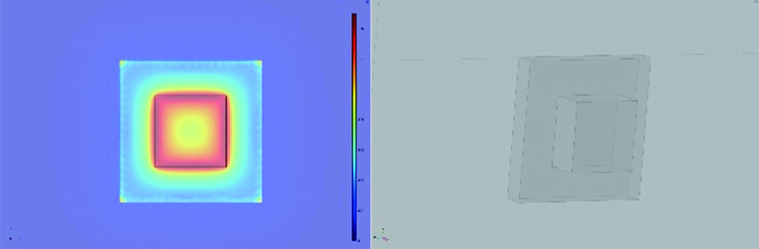 Fig. 1. Force analysis of N52 neodymium magnet under ideal conditions.
This is one of the highest available magnet grades in the market. However, the weight of one magnet at 626 g is also high.
The model comprises one N52 magnet, one steel plate (100 mm × 100 mm × 15 mm), and one iron yoke of the same size as the plate.
With the geometry shown in Fig. 1 and with material properties listed in Table I, COMSOL simulations computed the force as 1156.8 N (close to specified magnet technical specifications, thus validating the model). It is shown in [8] that adding a yoke of high permeability to close the magnet circuit from one side results in a significant increase in adhesion force on the other side. The results showed that adding an iron yoke of the same size as the steel plate increases the force to 1663.3 N. This model was used as a base model to build an App using the COMSOL Application Builder. The App window is shown in Fig. 2.
 Fig. 2. FEA analysis using COMSOL App.
TABLE I. PROPERTIES USED TO INVESTIGATE ADHESION MODULES FOR COMSOL SIMULATION
| Properties | Value |
|---|---|
| Magnetic induction intensity Br (T) | 1.47 |
| Magnetic coercive force Hcb (KA/m) | 796 |
| Relative permeability of magnet (μr) | 1.05 |
| Relative permeability of steel plate | 1000 |
| Relative permeability of iron yoke | 4500 |
An optimization process was performed using COMSOL by varying the physical parameters of the magnet-yoke adhesion module [6]. The parameters that varied were the size of the magnet and relative permeability of the ferromagnetic structure. The air gap (distance between ferrous surface and magnet) is another important parameter to design an adhesion system for complex structures [6,7]. The best magnet configuration for maximum adhesion force [5] uses three magnets with N–S–N orientation placed on an iron yoke (Fig. 3).
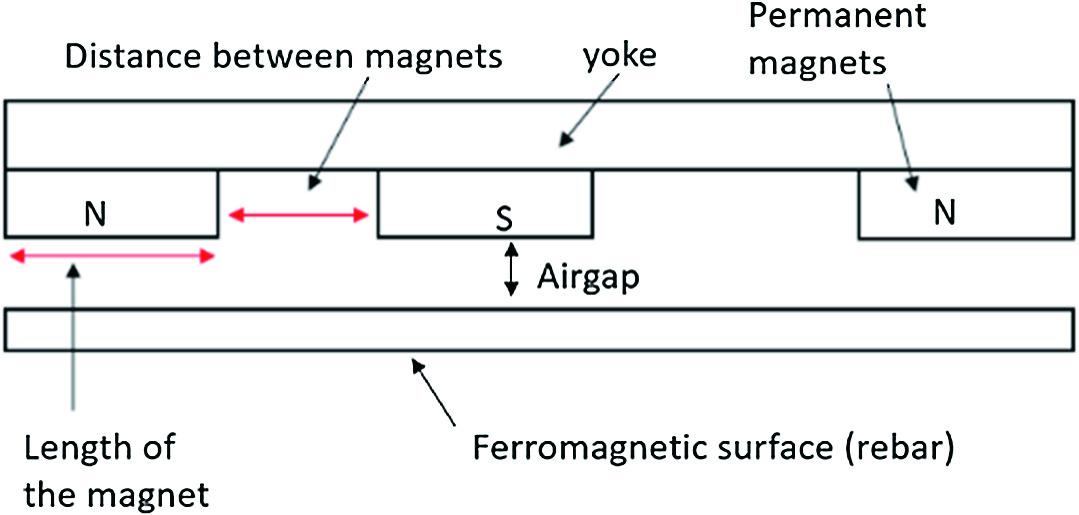 Fig. 3. Magnet yoke modeling layout.
The simulation model is composed of an iron yoke (250 mm × 50 mm × 10 mm, approximately 960 g net weight); three N52 rare-earth neodymium magnets are arranged on top of the yoke in an N–S–N configuration with 50 mm spacing.
Simulating this magnetic adhesion system (yoke + three magnets) placed over a 12 mm steel rebar with 30 mm of air gap (concrete cover) predicts an adhesion force of 143.1 N. The magnetic flux lines are shown in Fig. 4. The simulation was validated with an in-house experimental test rig. Setup and results are explained next.
 Fig. 4. Magnetic flux line behavior of three N52 magnets arranged N–S–N.
C.EXPERIMENTAL RESULTS WITH IN-HOUSE TEST RIG
Fig. 5 shows the positioning of the magnets on the yoke to construct the adhesion system simulated in Section II.B. The weight of the magnet system was 2.83 kg, measured with an industrial scale.
 Fig. 5. Construction of the magnet system.
An attachment was added to the iron yoke to be able to fix it on the load cell machine that performed the force/tension test. The Instron 5567A B723 machine (capable of measuring forces up to 2 kN) was calibrated, and the test was conducted in accordance with ISO 7500-1:2015. The Instron procedure used was N001.
The magnet system was placed at 200 mm from the rebar on the load cell machine (see Fig. 6). The distance was slowly decreased while approaching a 12 mm diameter rebar until a 20 mm spacing gap was left between the magnets and the rebar. Measured force data were recorded (six values per second). Measurements were repeated for 16 and 20 mm diameter rebars.
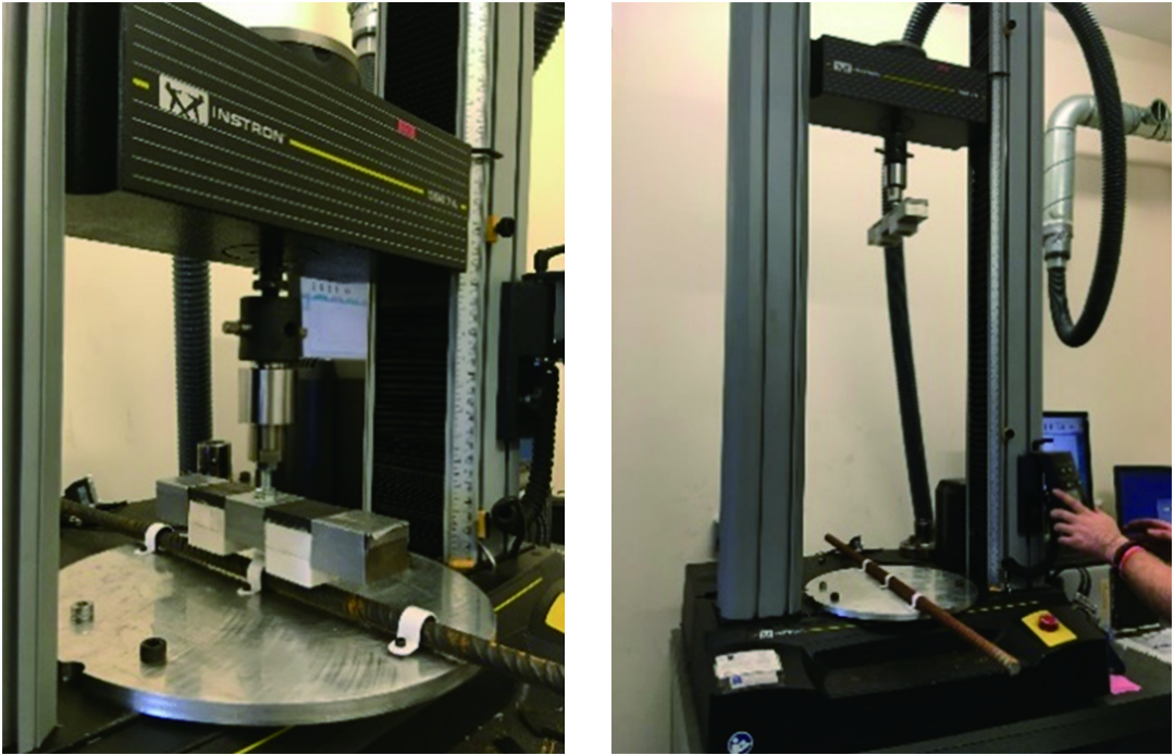 Fig. 6. In-house test rig using an Instron machine (2 kN tension/compression load cell).
For the sake of illustration, in the following sections, the results shown were performed on a 12 mm diameter rebar.
Most R/C structures have rebars within 30–35 mm beneath a concrete cover. However, concrete structures exposed to wet conditions have a concrete cover that can reach 50 mm. Therefore, adhesion force was predicted with simulation and experimental measurement for the increasing air gap to the rebar (see Fig. 7).
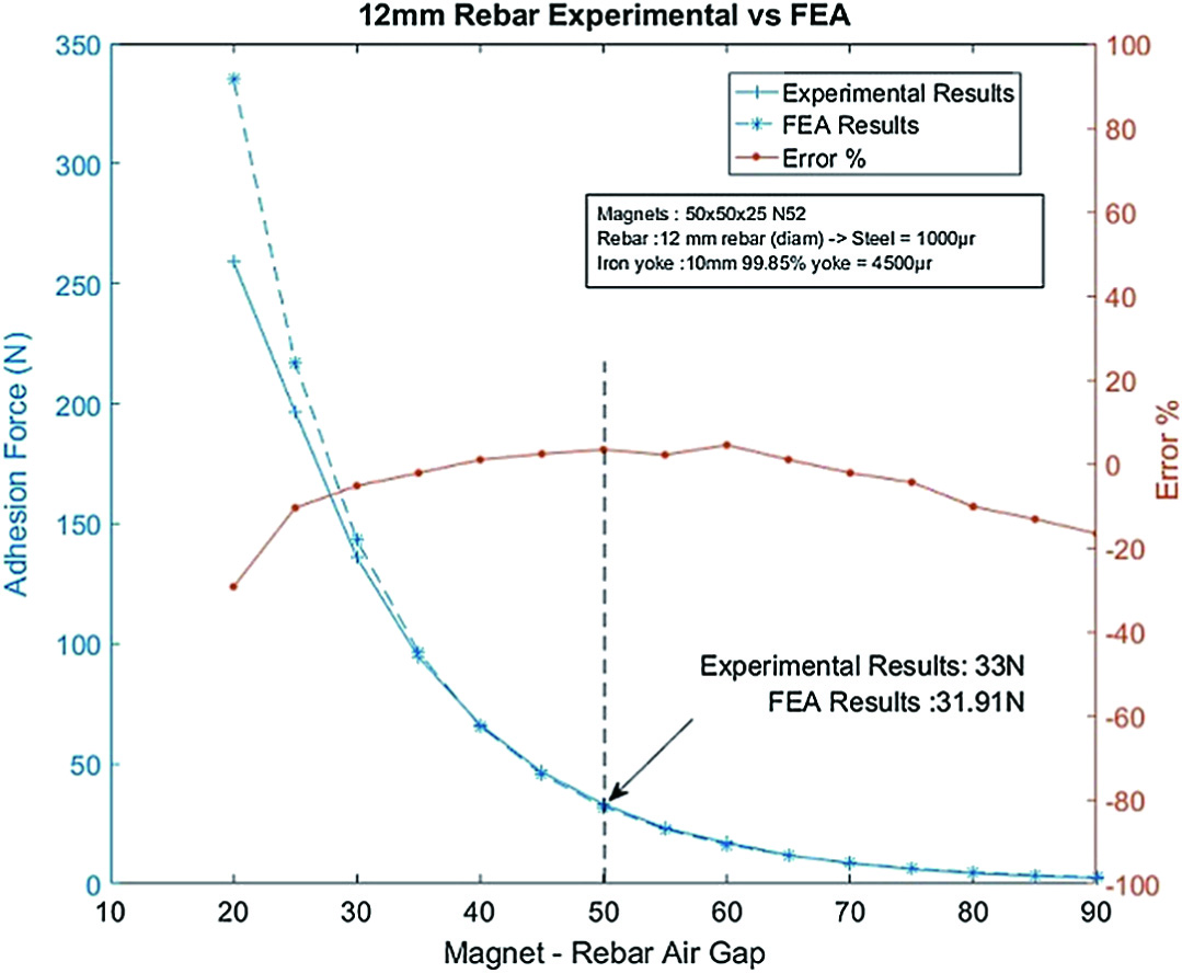 Fig. 7. Measured adhesion force and force predicted by FEA with COMSOL.
As expected, the adhesion force decreases rapidly with an increasing air gap, from around 100 N at 35 mm to only 31.39 N at 50 mm. Good agreement between experimental and COMSOL predictions validates the accuracy of the App.
When the air gap was 30 mm, a 5% error was recorded. Minimum error was recorded when the air gap was 40 mm (i.e., min error of 0.91%). Systematic errors can be the reason for the ±5% error (i.e., when considering the air gap vs. forces, ±1 mm can influence the adhesion force significantly). However, these results provide evidence to validate the COMSOL model and thus give confidence in the application.
D.ROBOT R/C POTENTIAL WORKSPACE: SIMULATIONS AND TEST RIG
In Section II.B, it is shown that the gap between the magnets and the rebars is the most important determinant of adhesion force. Nevertheless, other parameters such as the diameter, configuration of rebars (e.g., a mesh of rebars), and density of ferrous material also influence the adhesion force. British standard BS 850 and Eurocode [26] specify the minimum concrete cover over rebars for different environmental conditions. Most R/C structures are made of a mesh of rebars as shown in Fig. 8.
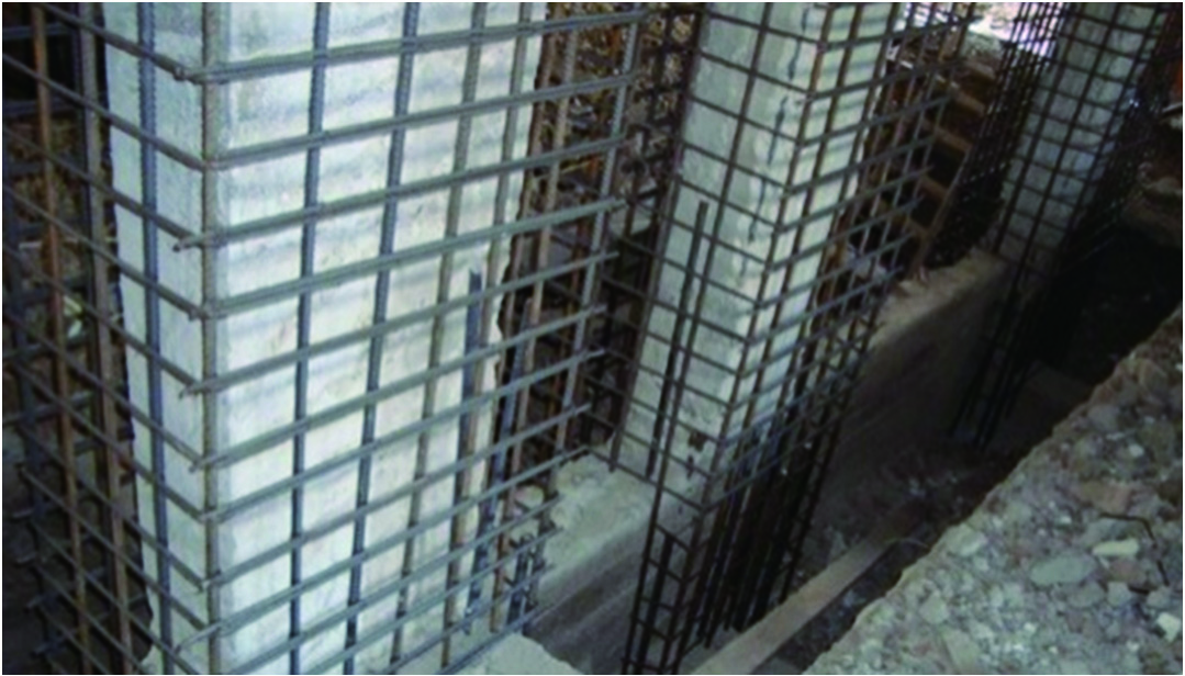 Fig. 8. Potential workspace for the climbing robot.
The force estimation application is improved by adding the possibility to choose from a set of rebars (mesh) as the ferrous surface. The gap distance between the rebars and the magnet system (concrete cover) can be changed directly from the application.
For this experiment, four different sizes of mesh were tested (see Fig. 9) with three different concrete covers. To cover a large ferrous surface and to achieve the maximum adhesion force, it was decided to develop an arrangement of three yokes in parallel at a distance of 50 mm between them. Magnets were arranged in the same way as in Section II.B. The results are listed in Table II. As expected, the closer the ferrous surface is to the magnets, the greater is the adhesion force achieved.
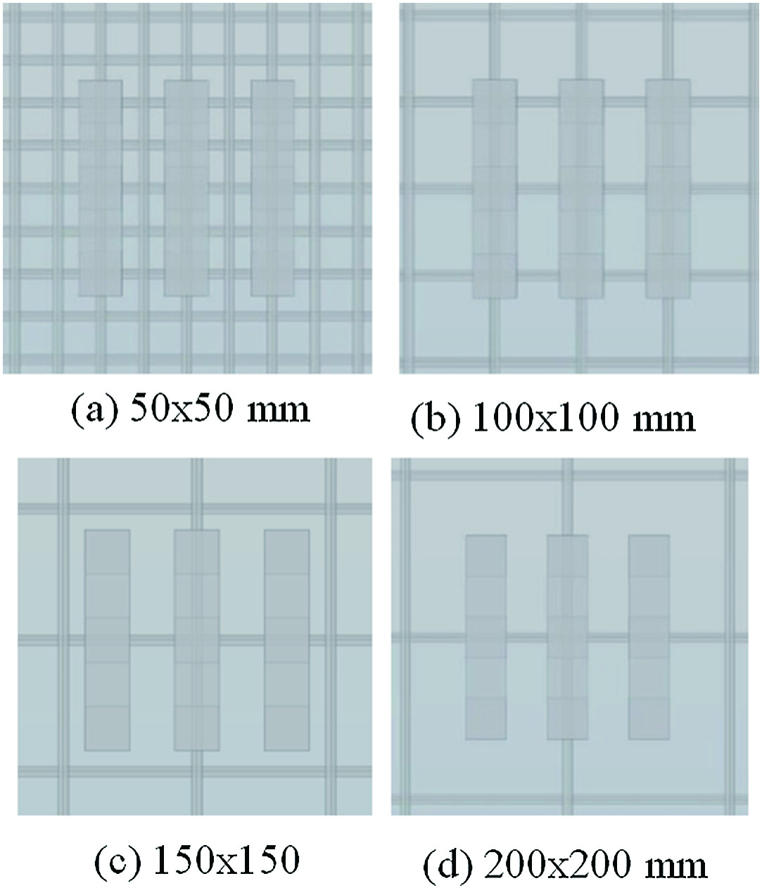 Fig. 9. Rebar mesh spacing in four configurations.
TABLE II. SIMULATION RESULTS WITH DIFFERENT MESH SIZES AND CONCRETE COVERS
| Mesh space 12 mm rebar | Force at 40 mm (N) | Force at 35 mm (N) | Force at 30 mm (N) |
|---|---|---|---|
| 200 mm × 200 mm | 116.7 | 159 | 225.9 |
| 150 mm × 150 mm | 145 | 192.6 | 263.3 |
| 100 mm × 100 mm | 252.2 | 352.6 | 506.3 |
| 50 mm × 50 mm | 287.9 | 391.4 | 546.8 |
The aim of this experiment was to determine the type of rebar mesh where the robot will be able to climb as well as its payload capacity. To validate the simulation results, a magnet system consisting of three yokes was attached to aluminum brackets as shown in Fig. 10. The weight of this system was 10 kg.
 Fig. 10. Test rig construction with four load cells.
To measure adhesion forces, OMEGA mini load cells were attached to each of the four corners. Using an OMEGA summing box and a compatible meter, the total adhesion force applied by the magnet system was measured.
A dynamic rebar wall was constructed where it was possible to change the spacing between rebars. Three mesh configurations using 12 mm diameter rebars were made possible. The rebar meshes were covered with a fixed plywood board to simulate a concrete cover of 30 mm (the relative permeability of dry concrete is practically the same as air and wood). Load cell measurements were recorded with the constructed magnet system placed over the dynamic wall. Comparison of adhesion force measurements performed on the test rig results and predicted forces by FEA from the COMSOL simulation are tabulated in Table III.
TABLE III. ESTIMATION OF THE ROBOT’S WEIGHT WITH THE PROPOSED MAGNETIC ADHESION SYSTEM
| Mesh space with 12 mm rebar | FEA magnet force (kg) | Load cells force (kg) | Max payload at 30 mm (kg) |
|---|---|---|---|
| 200 mm × 200 mm | 23.03 | 24.14 | 8.82 |
| 100 mm × 100 mm | 51.62 | 50.91 | 22.20 |
| 50 mm × 50 mm | 55.75 | 61.82 | 27.66 |
If coefficient of friction is 0.5 and the total weight of the adhesion system is 10 kg, an estimation of the robot’s payload capacity is calculated in the last column of Table III. See analysis in [4].
E.REAL ENVIRONMENT TESTING: CAR PARK
Results from the above experiment give us the confidence to apply the adhesion system to a real-world environment. It is a well-known fact that the columns in multistory car parks are well reinforced.
Because a reliable method to determine the size of the rebars or their distance was not available, in the first instance, the system was placed on the column to verify that it remained stationary and stuck to the column. Once confirmed that the system was holding, additional weights were incrementally added to the system, as seen in Fig. 11, until the system started sliding.
 Fig. 11. Test on a real reinforced concrete structure: car park column.
Although it is not known how much ferrous material was embedded in the car park column, it was established that a robot using this adhesion system will be able to carry a payload of 7.6 kg.
III.CRAWLER’S DESIGN: THE PAYLOAD
Structure of the physical robot, CAD design, is illustrated in Fig. 12. The adhesion module was positioned under the robot to coincide with the rebars. The design was optimized with a series of computer-aided design tasks to maintain a balance between the robot’s physical parameters such as its weight, payload, and the adhesion strength of the magnet module.
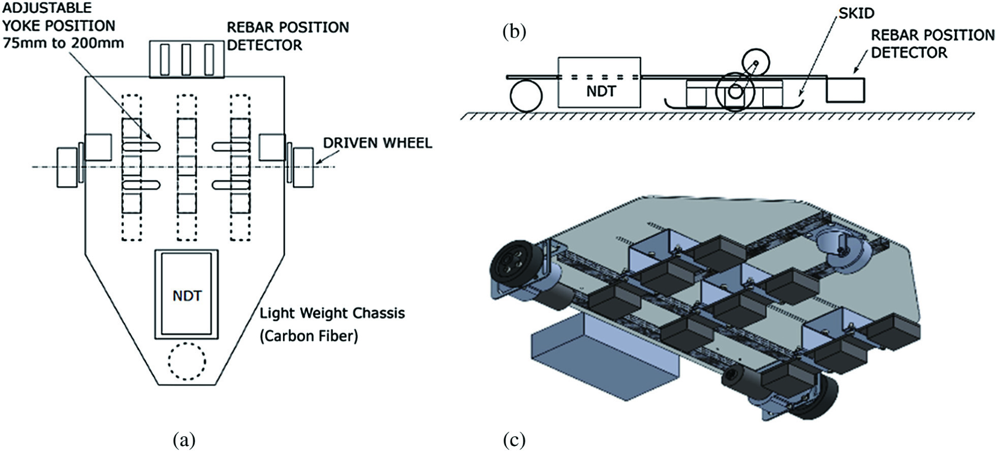 Fig. 12. (a) and (b) Schematic of the robot, (c) magnet system.
A.NDT MODULE: GPR
The GPR is an effective NDT method for concrete structures. This technique has been commercially available since the 1970s, and numerous studies have been carried out since to develop it for a wide range of concrete inspection applications. It offers a unique technique to characterize surface and subsurface features. Different types of defects can be identified in rebars and overlaid R/C decks. It is also used for thickness measurement of concrete members, air void detection, inspection of vertical R/C structures, mapping of reinforcement bar locations, and measuring material properties of concrete [27,28]. GPR offers the advantage of high scanning speed and being lightweight (<2 kg) and is thus eminently suitable for deployment on a climbing robot. However, its limitations are that it cannot detect delamination, honeycombing, grouting defects, or measure variation of the quality of concrete. While other NDT methods can detect these defects, they are impractical for deployment on a climbing robot because of weight or because they can only be used in a static position.
The SIRCAUR project has used the PicoR-2K GPR for the NDT of concrete structures (specification shown in Table IV). The device is designed for subsurface sensing and monitoring of opaque materials. It enables calculation of the thickness of the layers inside such materials as well as detection and positioning of in-homogeneities within the material.
TABLE IV. PICOR-2K GPR SPECIFICATIONS
| Parameter | Value |
|---|---|
| Frequency range (at a level of −10 dB) | 0.5–3.5 GHz |
| Central frequency | 1600 MHz |
| Pulse duration | 60 ps |
| Pulse amplitude voltage | 6 V |
| Pulse repetition frequency | 50 MHz |
| Range measurement accuracy | 1–2 cm |
A laptop running the PicoR 4.3 software was connected via a USB-C cable to the PicoR-2K GPR. A concrete test block was manufactured (Fig. 13) with various known degrees of rebar thinning and various sizes of air void, embedded at known depths from the block surface. The concrete test rig block was manufactured, and tests were conducted by project partner TWI.
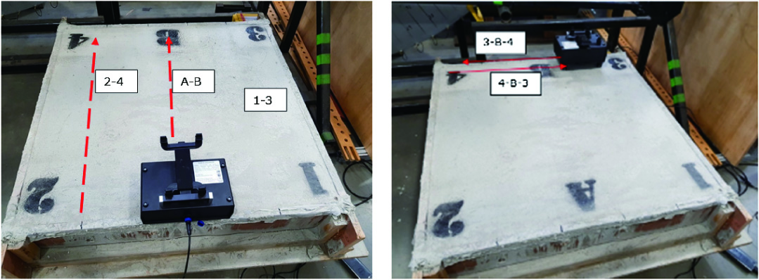 Fig. 13. (Left) Three scanning paths used to detect air voids. (Right) Scan paths 3-B-4 and 4-B-3 used to detect both air voids and rebars.
Three scanning sequences shown in Fig. 13 were used to detect (a) air voids: GPR moved in directions 1-3, A-B, and 2-4. These paths avoided the rebars but passed over the voids created within the concrete block; (b) rebars: GPR moved in directions 1-A-2 and 3-B-4.
These paths avoided the voids but passed over rebar defects; (c) rebar and voids: GPR moved in the direction of 3-B-4 and then from 4-B-3. These trials evaluated the GPR with tightly spaced defects. Results are illustrated in Fig. 14.
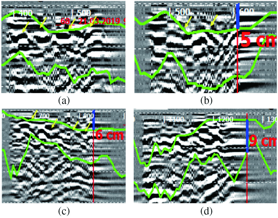 Fig. 14. (a) Scan path A-B, (b) scan path 2-4, (c) GPR detects four rebars, and (d) scan path 4-B-3.
Explanation of Fig. 14: (a) scan path A-B: four air voids detected in the scan line. Constant peak heights indicate that the voids are at the same depth; (b) scan path 2-4 detects two of the three defects in the scan; (c) GPR scan detects four rebars in the concrete block (downward trend of the peaks indicates that the rebars are positioned at increasing depths); (d) scan path 4-B-3 detects both rebars and air voids. The upwards peak trend indicates that the scan moves from an area where the rebars and voids are at a lower position to an area where they are at a higher position.
B.THE PROTOTYPE
The climbing robot prototype is illustrated in Fig. 15. The design was performed by project partners InnotecUK with the support of TWI and LSBIC. The aim was to keep the whole robot payload including the electronics and the NDT system to less than 20 kg. Therefore, the chassis of the robot was made of carbon fiber and aluminum alloy. The robot’s control was robot operating system (ROS) enabled using a Raspberry Pi.
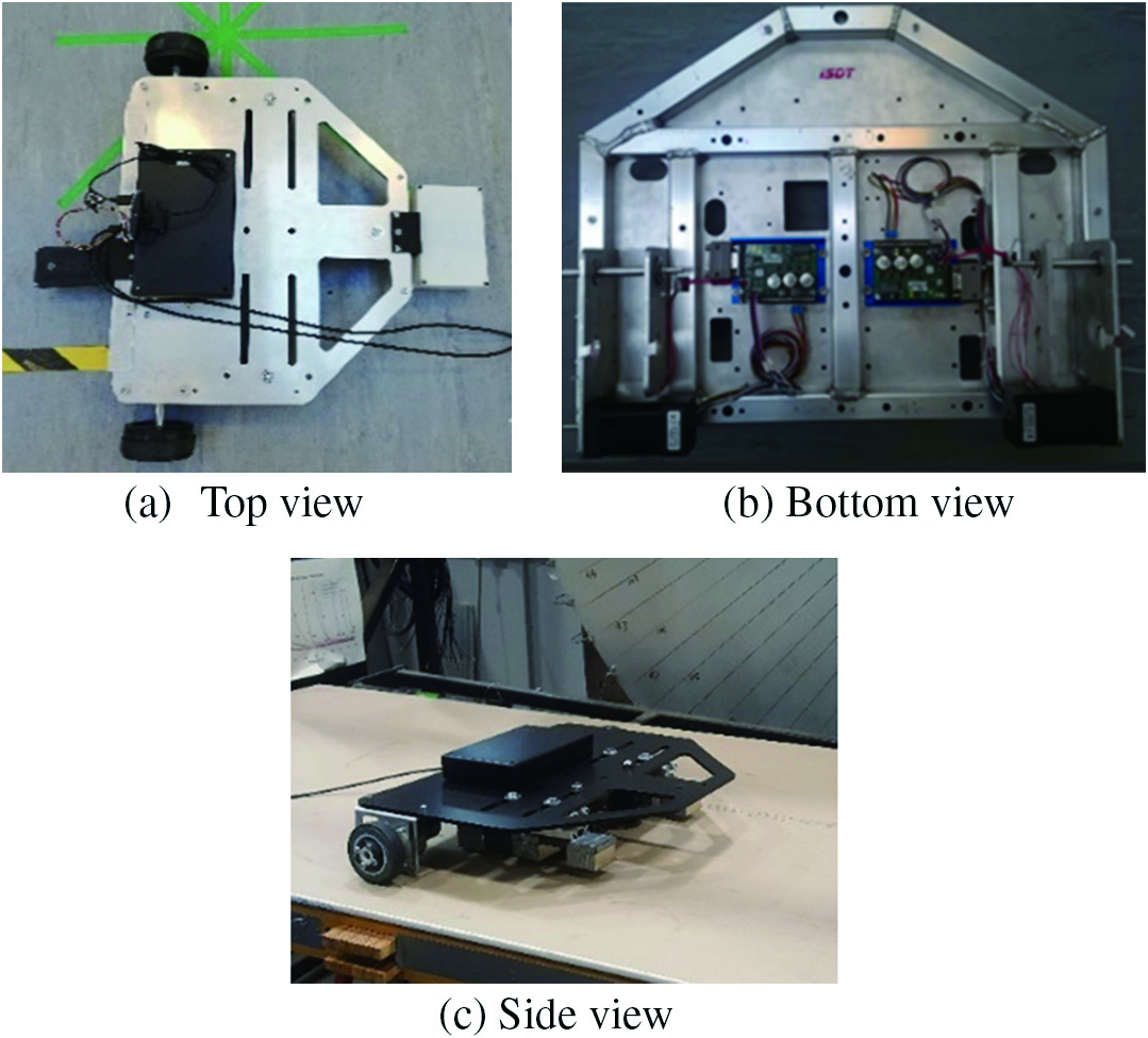 Fig. 15. Climbing robot, top, bottom, and side views.
A laboratory test climbing surface was created by developing a wall with the same rebar spacing as the simulations. Fig. 17 shows the dynamic wall (described in Section II.C) constructed to perform the trial test. Two climbing tests were conducted with the wall placed horizontally, and the climbing robot placed underneath as shown in Fig. 16, and the wall erected vertically as shown in Fig. 17.
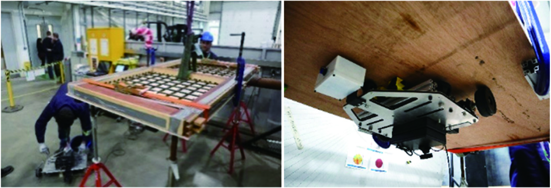 Fig. 16. (Left) The wall placed horizontally. (Right) Climbing robot on the wall showing that the adhesion force is sufficient to support the payload.
 Fig. 17. Climbing robot tested on the vertical wall.
The final configuration used for the trials was with 100 mm × 100 mm rebar mesh and 12 mm diameter rebars. Trial with the crawler upside-down showed that the magnetic adhesion force provided by the permanent magnets was enough to support the weight of the SIRCAUR robot.
C.THE LOCALIZATION MODULE
A localization system was developed that used the ultra-wide band (UWB) localization technique to provide an accurate measurement of robot position on the wall. The system used the commercially available POZYX™ UWB module which was compatible with the operational microcontroller used for control purposes.
A ROS node was developed to incorporate the localization module into the robot’s software architecture. The four beacons of the POZYX system can be seen in Fig. 17 at each of the four corners on the wall, which enabled the successful location of the robot on the wall.
IV.CONCLUSION
SIRCAUR is a lightweight, fast-moving climbing robot system for the inspection of R/C structures which is easy to deploy and retrieve. The entire structure of robot is built with aluminum alloy and carbon fiber to make it lightweight. Robot structural integrity has been assured with a series of structural analysis experiments using CAD design software (SolidWorks) and FEA software (COMSOL). Adhesion force to carry the robot payload has been optimized by using configurations of neodymium 52 magnets placed on yokes of high permeability with force predictions made with COMSOL FEA simulations and validated experimentally.
A GPR NDT sensor has been incorporated into the system to detect the presence, location, and depth of rebar and air voids in a concrete structure. Laboratory trial tests on a wall engineered to simulate different rebar meshes and rebar depths indicate that the climbing robot can climb on concrete walls when the air gap between the magnet system and rebar is 30–35 mm. The adhesion force generated by the permanent magnet system does not require an energy supply and is, therefore, advantageous for a climbing robot performing NDT on large concrete structures. The GPR system has been shown to detect rebars and air voids and measures both their position and depth.