I.INTRODUCTION
Structural integrity is important for safe operation of engineering structures and industrial facilities. In a wind turbine, the wind turbine blades (WTBs) are critical components whose structural failure may result in catastrophic consequences even 100 m away from the site if, for example, part of a WTB flies away. As wind turbines are expected to generate electricity 90% of the time during a typical lifetime of 20 years, structural flaws in WTBs are of great concern [1]. Cracks in the blades sometimes appear soon after manufacture. Defects can also be produced during transportation. Repairing or replacing a WTB is always difficult, especially for large wind turbines. The downtime of a wind turbine installation due to a blade failure usually lasts 4–6 days, which is longer than for repairs due to electrical or mechanical failure within the nacelle. Therefore, WTBs require regular inspection and maintenance to ensure defects caused or developed during operation can be found at an early stage. Otherwise, small defects beneath the surface may develop into large ones, possibly leading to a catastrophic accident. Thus, engineers and scientists are looking for various methods to conduct nondestructive evaluation (NDE) of WTBs after installation on a wind tower.
Numerous NDE techniques have been widely used in industry but are limited in their application to the inspection of in-situ WTBs. Ultrasonic testing is a point-wise contact inspection technique and is usually only suitable for homogeneous materials, hence, is difficult to apply to on-site inspection of WTBs. Radiography, especially computer tomography, is a powerful technique widely used in industry. However, its deployment to a wind tower is difficult. Thermography is a promising NDE technique, but its application to on-site WTB inspection is yet to be realized, given the environmental temperature change due to wind flow which adds considerable noise to the captured thermal images.
Shearography as an optical technique and has the main advantages of noncontact and relatively large area of coverage in a single inspection. It was first proposed by Leendertz and Butters in 1973 [2] and was further developed by Hung et al. [3]–[5]. Compared to other optical techniques such as holography interferometry, moiré interferometry, and electronic speckle pattern interferometry (ESPI), shearography has a relatively large tolerance to vibration, enabling it to operate beyond an optical lab. Thus, shearography has been recognized as a powerful inspection technique and has found wide application in a range of industries including the aerospace, automotive, and shipbuilding sectors. Guelker [6] used shearography to inspect buildings and monuments and obtained better results in comparison to other nondestructive testing methods. Hung [7] has pointed out that shearography is more suitable for inspecting composite material because of its capability of measuring the derivatives of the displacement and is more sensitive to strain variation. Niezrecki et al. [8] have given a systematic comparison of five NDE methods based on a CX-100 blade sample for their performance. In their tests, shearography has shown better results in terms of full-field identification of flaws and subsurface defects. Likewise, a detailed comparison between different NDE techniques for WTB inspection has been summarized by Yang et al. [9]. They have listed visual, ultrasonic, optical, electromagnetic, thermographic, and radiographic methods to evaluate the most suitable NDE for WTB. Hung et al. [10] have developed fringe analysis and phase-shift techniques for interpretation of shearography results, where typical butterfly fringe patterns indicate stress concentration caused by subsurface defects. By adopting phase-shift technique [11], quantitative phase maps could be retrieved for further evaluation. Phase shift could be temporal and spatial based on different phase-shift mechanisms. Temporal phase shift [12,13] is widely used for phase mapping and can yield relatively clearer results than spatial phase shift. However, the temporal phase shift is usually only suitable in static or semi-dynamic conditions and not in dynamic conditions such as on a wind tower [14]. Spatial phase shift requires more computational processing, and the hardware is much complicated. Nevertheless, it is tempting to develop spatial phase shift as a real-time measurement technique in demanding industrial conditions [15].
It should be noted that all existing shearography techniques are operated on the ground, and their application for on-site inspection of a WTB has not been demonstrated. The WTB is subject to constant vibration due to wind. Therefore, a solution for shearography to work on a wind tower is to attach it on the WTB surface during inspection, so that the relative motion between the shearography and the WTB is within the tolerance of the shearography system. The integration of NDE equipment with a robotic carrier or climber is the trend in industry. In fact, for application to WTBs, there are various choices of on-the-shelf robotic systems which can carry simple monitoring equipment such as visual inspection [16]–[18]. However, to the authors’ knowledge, there are no reports showing a practical robot-assisted shearography for on-site WTB inspection. The ultimate goal is to develop a robot-assisted shearography system which is able to inspect the WTBs on-site with, for example, remote control by operators on the ground (for onshore wind turbines) or on a vessel (for off-shore wind turbines), thus, not requiring human inspectors on the wind tower to do the inspection. This paper reports part of the research work surrounding the design of a new shearography system integration with a robotic climber for on-site WTB inspection. The rest of the paper is structured as follows. Section II presents the design principle of shearography. Section III provides the detailed methodology, including the processing algorithms, the robotic climber, and test results. Test results of the system on blade samples are presented in section IV. Section V presents feasibility study of post processing of phase-shift analysis and laser heating for future development. The paper is concluded in section VI.
II.SHEAROGRAPHY PRINCIPLE
Shearography or the so-called digital shearing speckle pattern interferometry (DSSPI) and its related systems such as ESPI [19] are based on different optical interferometers, which split a single laser beam in a constant frequency into two beams to produce coherent light, hence to derive interference fringes for NDE inspection [20]. Unlike holography [21], the specific pattern of butterfly depicts derivatives of the deformation. In this section, the shearography set-up and its calculation are described.
A schematic description of shearography system is shown in Fig. 1(a). The sample surface to be tested is illuminated by an expanded laser beam with sole wavelength. The light scattered from the object surface passes through a Michelson interferometric prism, and it is split into two beams, see Fig. 1(b). The divided beams are eventually focused on the image plane of an image shearing charge coupled device (CCD) camera, where a personal computer (PC) is connected for real-time monitoring. By turning mirror 1 in the Michelson interferometer at a very small angle, a pair of sheared images of the object is generated on the image plane of the CCD camera. The two shearing images interfere with each other forming a speckle interferogram on the PC side. The intensity of the interferogram could be expressed as
where a is the background intensity, b is the modulation term, and ϕ is the phase current time. After deriving the speckle pattern, the system processes the loading on the surface at time T. With the deformation of the surface, the phase of the speckle pattern is changed to form a new speckle pattern, which could be expressed using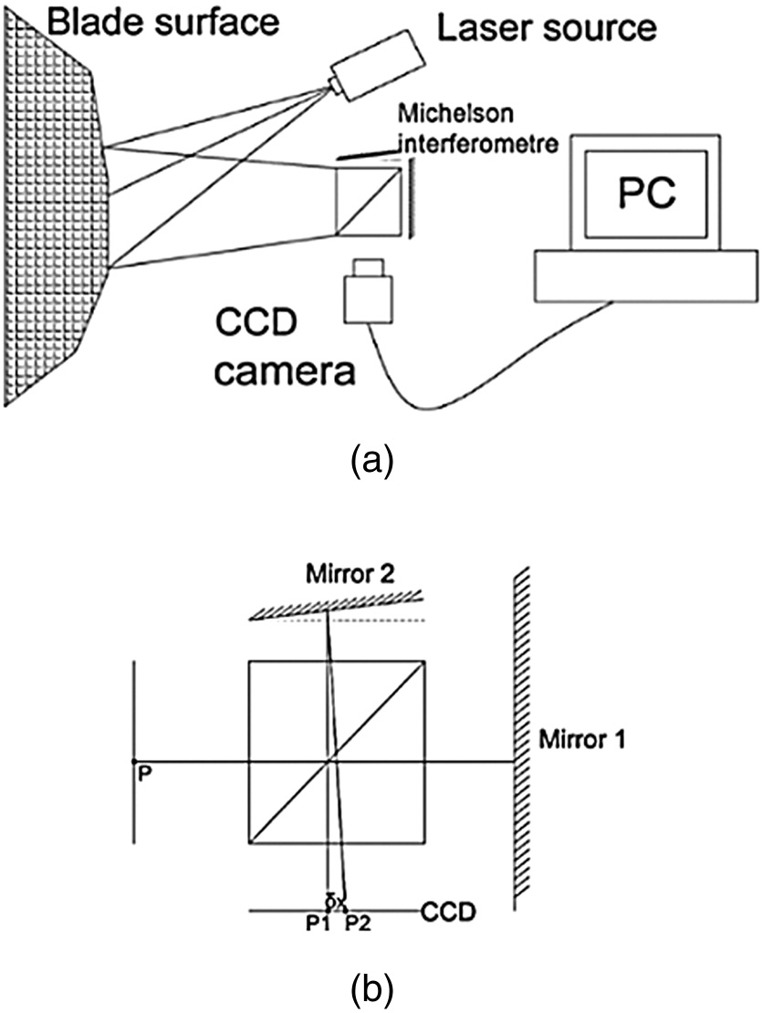 Fig. 1. Schematic diagram: (a) Shearography set-up and (b) Michelson-based interferometric prism.
Fringe pattern at time T could be derived by subtracting (1) from (2) resulting in
The term is the background phase and is high-frequency carrier. Likewise, the term is the low-frequency carrier. From the geometry mechanism of the laser light path, the phase difference [20] can be expressed as
which denotes that the phase difference on the fringe pattern or phase map is proportional to the first derivative of the defamation in the specific direction.III.METHODOLOGY
A.SHEAROGRAPHY DESIGN AND REALIZATION
The current shearography systems have mostly concentrated on phase-shift techniques. The widely mentioned phase-shift techniques are temporal phase shift [12,13], which requires static conditions for processing. Although dynamic phase shift [14] is currently being researched, it still requires several seconds to initiate the reference within fully static condition, and this is not practical for utilization of shearography on a WTB because in the initialization process, the ambient condition is unpredictable and mostly is fully dynamic. For this reason, temporal real-time phase shift is hard to accomplish with automatic manoeuvringon-boarda WTB. Spatial phase-shift techniques, in contrast, require relatively expensive and complicated hardware configuration as well as extensive computational effort.
To date, the most practical real-time NDE based on shearography is the subtraction of speckle patterns before and after loading. The shearography process is shown in the flow chart of Fig. 2.
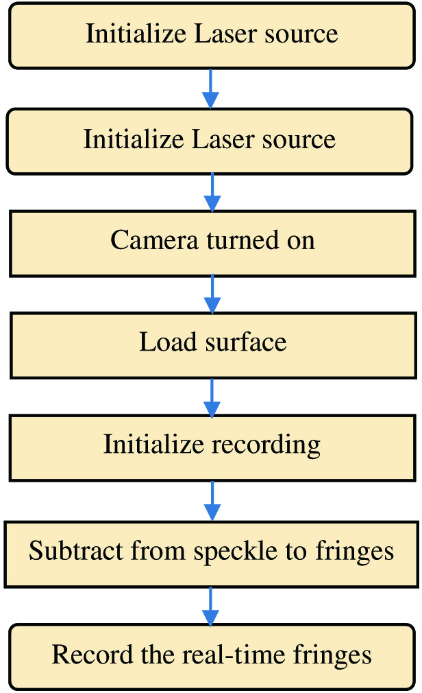 Fig. 2. Shearography working flow chart.
The design of the shearography unit uses an upper mirror to reflex the laser from the window of the main unit. The design is to fit the direction with the robotic climber, which will be introduced hereinafter. The developed shearography unit is intuitively shown in Fig. 3(a). The light path is shown in Fig. 3(b). The reflection mirror installed over the window of shearography unit is to enlarge the light path for the purpose of enlarging the field of view to enhance the efficiency of the whole inspection process. The specifications of the shearography inspection unit with the detailed technical parameters are shown in Table I.
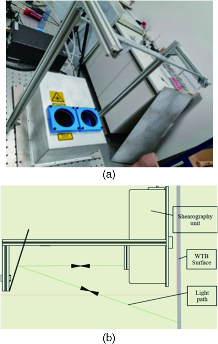 Fig. 3. (a) Shearography unit and (b) shearography light path.
Table I. SHEAROGRAPHY UNIT SPECIFICATIONS
| Items | Value | Unit |
|---|---|---|
| Laser output | 368 | mW |
| Laser wavelength | 532 | nm |
| Diffusion angle | 20 | degree |
| Total light path distance | 1.5 | m |
| Inspection area | ∼0.25 | m2 |
| Camera resolution (h × v) | 1600 × 1200 | px |
| Camera optical class | 1/1.8 | px |
| Camera pixel size | 4.5 | μm |
| Camera lens focal length | 25 | mm |
| Camera lens maximum aperture | f/1.4 | — |
B.LOADING METHOD
An aspect of shearography unit is the method of loading the sample surface [22]. Commonly used loading methods include force, vacuum, lamp, and hot air flow. Force and vacuum-based methods are used more in static conditions because they could last the load condition for longer period of time. However, force and vacuum are not practical for automatic NDE application on a WTB because the control of force and vacuum pressure is difficult to realize on-board the WTB by integrating with a robotic platform. Lamp is considered to have less control complexity in comparison to the above two methods. However, the heat exerted on the WTB surface is not as efficient as the hot air flow. Moreover, the weight and size of a lamp is much higher than a hot air flow equipment. Therefore, a heat gun was used for the loading process in this work.
C.ROBOTIC CLIMBER
The proposed robotic platform on the market to be adopted is the ICM (International Climb Machine, USA) robot VT 610, redeveloped by Dekra. The reason for using this robotic platform for the work is that it is easy to manipulate with remote control. Most importantly, the payload of this robotic climber is the largest to be found on the market. The attachment mechanism on vertical surface is a vortex system with an on-board large power motor, which provides a large amount of negative pressure for a maximum payload of 20 kg. This payload of the climber for shearography system is enough to initiate the NDE inspection work. Tests carried out have shown that it is robust enough for working on-board WTB. Fig. 4 shows an image of the field test of the robotic platform for its climbing and manoeuvring task. Table II shows the technical specifications of the robotic climber.
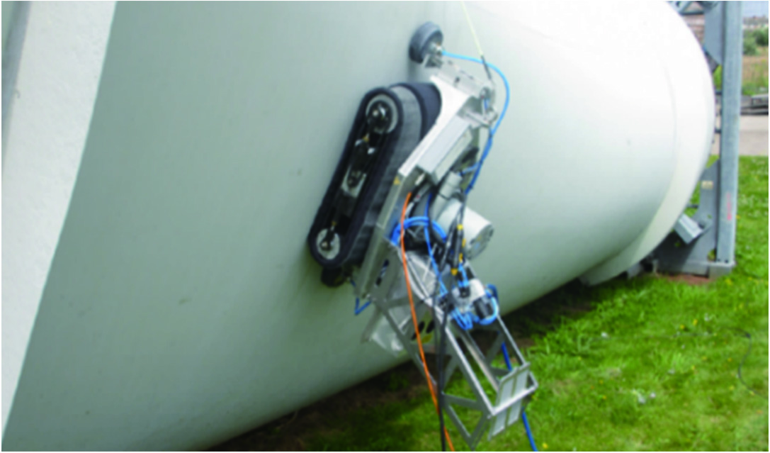 Fig. 4. Robotic system in-field test.
Table II. ROBOTIC CLIMBER SPECIFICATIONS
| Items | Value | Unit |
|---|---|---|
| Weight | 18 | kg |
| Payload | 22 | kg |
| Pull-off strength | 100 | kg |
| Chamber Pressure | 18.6 | kPa |
| Length | 610 | mm |
| Width | 610 | mm |
| Speed | 80 | mm/s |
Shearography as an optical inspection method is likely to be subject to the vibration of the material caused by different circumstances. In this case, the possible influence is the vibration from the wind. The selection of the ICM climber is the key solution to tackle this issue. The original vacuum force generated by the climber is enough to withstand high wind. However, considering the vibration caused by the vortex motor is also possible to damage the inspection results, a new redesign of using a separate pneumatic system with two suction cups attaching on the blade has been made to entirely eliminate the relative motions between the shearography unit and the WTB surface. The integrated system needs to conduct the inspection work below or equal the moderate breeze, i.e., level 4 under Beaufort wind scale considering the safety aspects. The description of this wind scale is the movement of the limbs of a moderate tree. A manual test of tugging and pulling with human force has been conducted to simulate the wind force greater than strong breeze, which is Beaufort level 6, i.e., movement of strong branches. The manual test has justified that both the original vortex vacuum and the new designed pneumatic system are able to hold the shaking from a strong male.
IV.SHEAROGRAPHY TEST ON BLADE SAMPLES
A.TEST PROCEDURE
The shearography unit and test samples are fixed vertically on a tripod and table. The conditions are changed to simulate the environment change on-board WTB. Parameters of the change of conditions include heating time frame, heating distance, exposure time, and ambient light intensity. Fig. 5 shows the experimental set-up of the system.
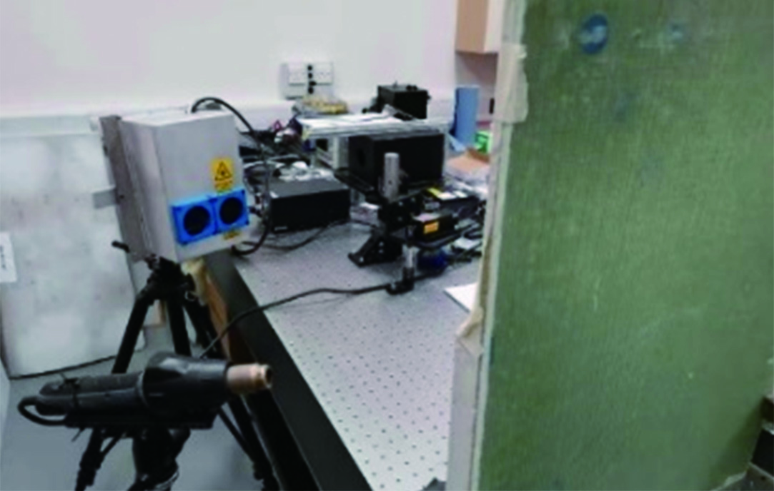 Fig. 5. Test of shearography set-up.
Two samples with different defects in different positions were tested. Sample 1: SC-45-6 sandwich composite panel from Renewable Technical Services Ltd (RTS) with the lamination skin thickness of 6 mm. Sample 2: SC-45-3 sandwich composite panel from RTS with the lamination skin thickness of 3 mm.
B.TEST RESULT AND DISCUSSION
From the test of different samples, subsurface defects could be interpreted by the variation of the fringe pattern on the intensity map captured by the CCD camera. Fig. 6 shows several example defects captured by the shearography system, in which the appearance of butterfly patterns indicates the typical delamination often occurring on WTB subsurface. As can be seen in the labeled red circles, obvious dual closed-loop pattern which implies the appearance of defects in the subsurface of the sample after the loading process. Combining the principle of shearography, which detects the first derivative of surface displacement, inference could be drawn that there exist defects in the subsurface of the sample with the type of delamination at the labeled positions. In this case, the shearography is a tool of mainly detecting the existence of the defect in the subsurface. The quantitative measurement of the defects, e.g., size and depth, will be integrated with phase-shift techniques and other NDE tools such as thermography and radiography.
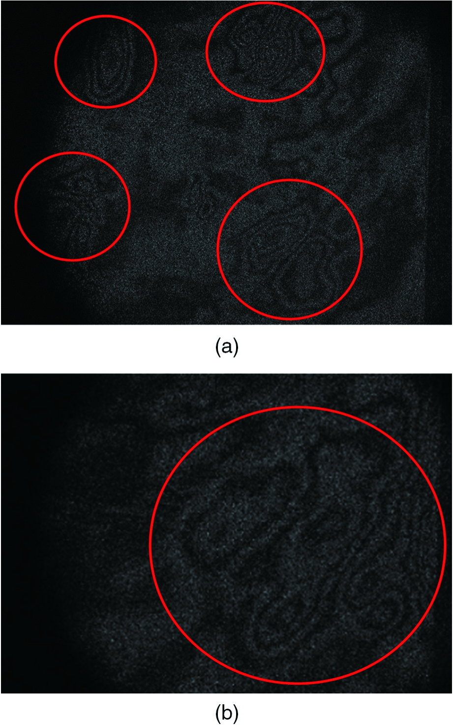 Fig. 6. Sample test fringe patterns: (a) Butterfly fringes on SC-45-3 and (b) butterfly fringes on SC-45-6.
Through the verification test of the shearography, the largest impact of condition variation is the loading process, including the heating time and heating distance. Larger heating power could exert more loading on the sample surface, and this will result in more distinction of the presence of butterfly pattern. Another condition change impacting the result is the ambient light. If the ambient light is large, the speckle pattern cannot be processed adequately as the reflected laser will be mixed with the light of other frequencies.
V.PHASE-SHIFT AND LASER HEATING
A.PHASE-SHIFT TECHNIQUES
Phase-shift technique is the future tendency of practice in shearography development. The current phase-shift technique is focused on four-step or three-step approach. Other dynamic phase-shift techniques are based on the basic stepping process but with different algorithms for fast calculations. Hereinafter is the verification of the feasibility of the phase shift applied on the existing system. The former system was added with a PZT actuator for the temporal phase-shift implementation. Four fringe patterns were derived from the subtraction between original speckle pattern and loaded speckle pattern. These are shown in Fig. 7(a). The fringe patterns went through Gaussian filter for optimization and smoothness, and these are shown in Fig. 7(b). The fringe patterns further went through the median filter, and the result is shown in Fig. 7(c). Notice that the test sample was also WTB sample with different subsurface defects. The quality of the fringe pattern is subjected to the loading process, laser beam power, and CCD camera. These data were obtained by applying the same heat flow as the loading process, which is more dynamic than only applying a force on the surface, such that the unexpected noise will be more than a simple model. For this reason, the optimization of the fringe pattern is regarded necessary as pre-processing of the phase calculation.
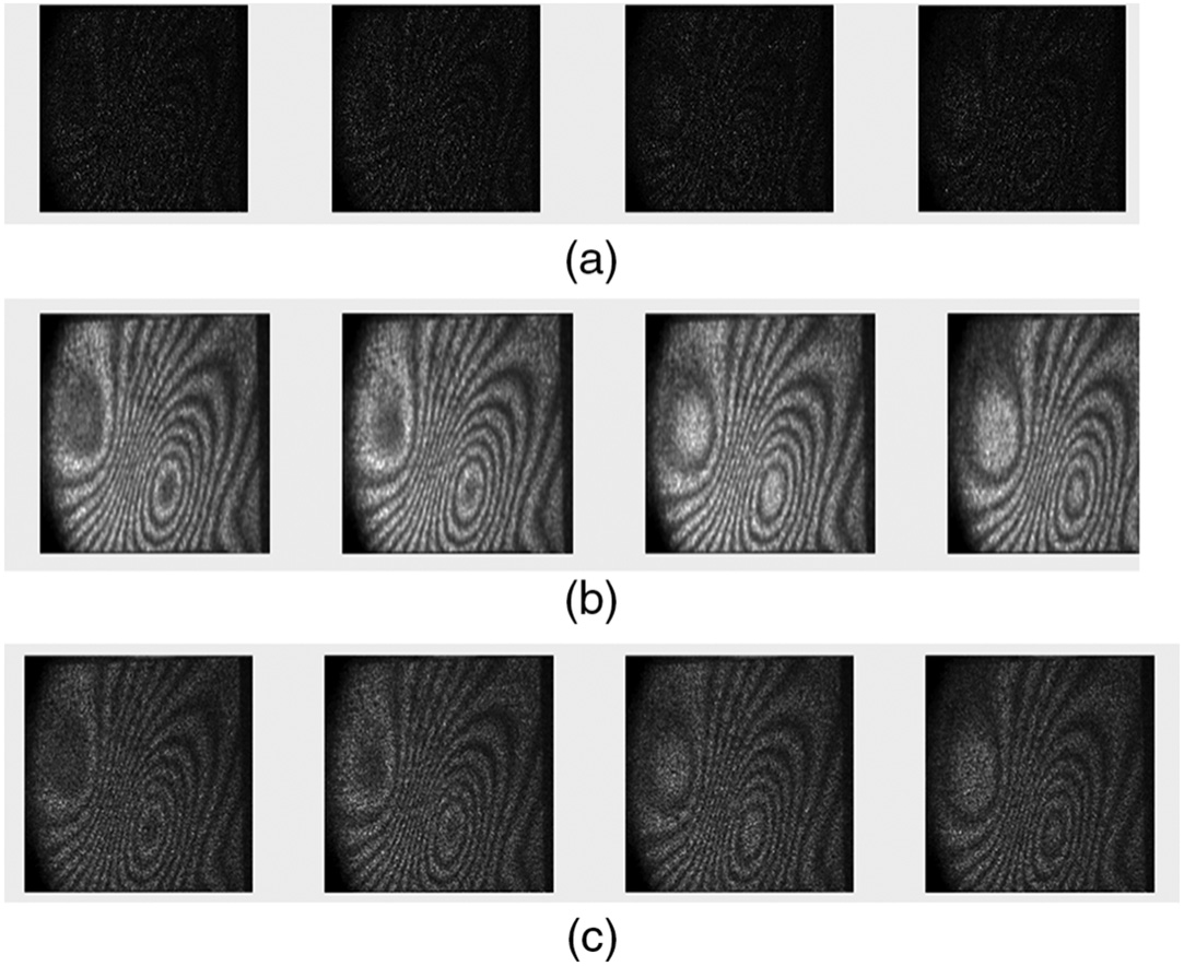 Fig. 7. (a) Fringe pattern, (b) its smoothing by Gaussian filter, and (c) its smoothing by median filter.
Phase calculation was implemented by adopting four-step phase-shift algorithm, and the result is shown in Fig. 8, where the images were processed by adopting the above three sets of fringes.
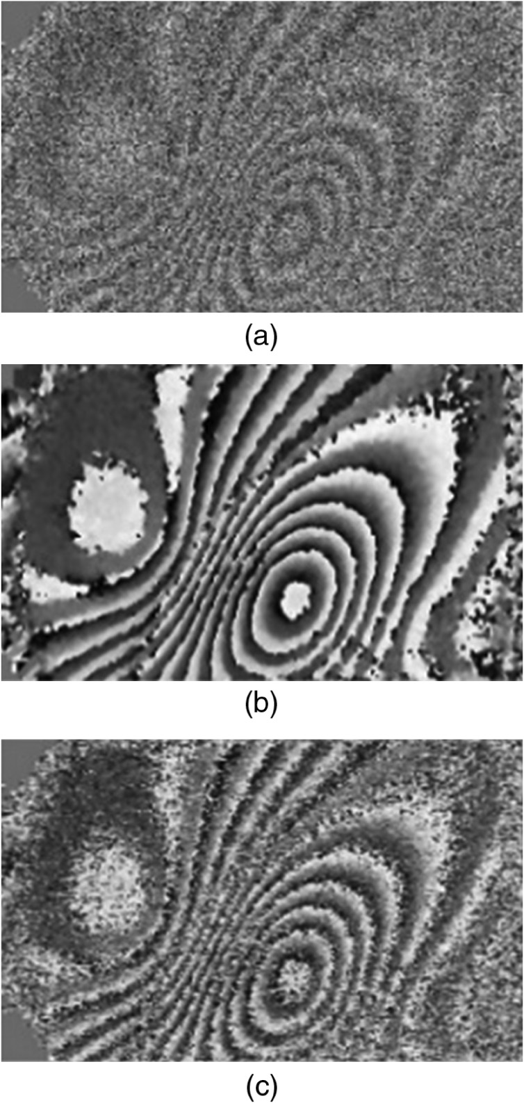 Fig. 8. Phase calculated by four-step phase-shift technique: (a) Phase from unfiltered fringes, (b) phase from Gaussian filtered fringes, and (c) phase from the median filtered fringes.
It is noted in the above results that the most ideal phase result is to use the Gaussian filter as a pre-processing method. It will be hard to obtain a desirable phase map from a fringe without filtering process due to relatively large levels of noise in comparison to the other two methods. The median filter is a commonly used method, and although the result is not as smooth as with using the Gaussian filter, the application is enough for industrial purposes.
To derive phase results with larger resolution, a further step is to filter the phase map. Fig. 9 shows the phase filtering results, in which the most suitable result for unwrapping is the one that went through Gaussian filter.
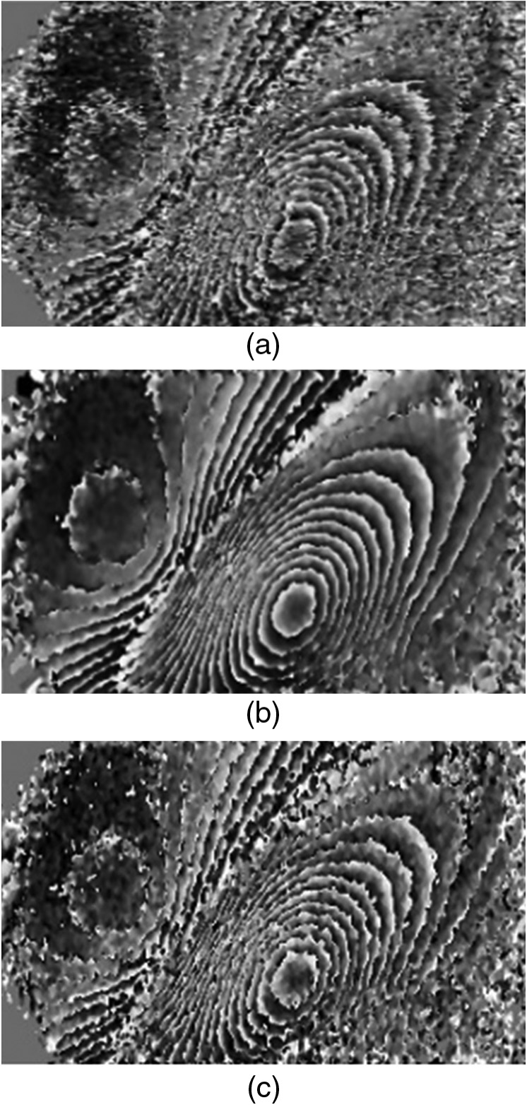 Fig. 9. Phase filtering from different phase maps: (a) Phase filtering from unfiltered fringes, (b) phase filtering from Gaussian filtered fringes, and (c) phase filtering from the median filtered fringes.
B.LASER HEATING LOADING METHOD
A high-power laser head with around 5 kW has been widely used in laser cutting and welding for different materials in industry. A proposed loading method using laser heating could also be used in the existing system, which aims to decrease the time of the loading stage to enhance the effectiveness of the whole inspection process. Moreover, deeper defects could be detected using laser heating because of the higher temperature rise in a short time. The intensity value on different laser heating heads could vary from 102 to 104 W/cm2. As for WTBs made of normal composite materials, large power lasers such as 5 kW could burn the surface in a few seconds. Thus, the best way to adopt laser heating in the loading process of shearography is to control the laser power and by producing a pulse from 1 to 2 s. Once the temperature has risen to around 10 °C, the laser will be paused for the shearography to record the surface change. Fig. 10(a) shows the set-up of the shearography system with laser heating as loading method for stiffer WTB samples. The sample used was mainly made of glass fibre for which the stiffness is higher than that of SC-45-6 and SC-45-3, and a section of the material can be seen in Fig. 10(b). The shearography system was placed half meter from the sample’s surface, the heating area using 5 kW laser was 0.5 m2 from 4 m distance, and the pulsed laser beam was expanded to further decrease the power to the sample surface.
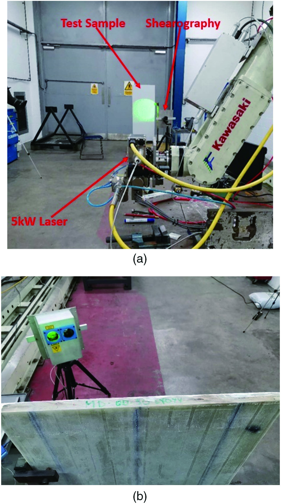 Fig. 10. (a) Laser heating shearography set-up and (b) sample for laser heating test.
The test used 1 kW laser power for 1-s pulse, and the shearography recorded the result. The temperature monitoring on the sample surface can be seen in Fig. 11. Note that the black centre surrounded by a white circle in thermograph in Fig. 11(b) is a contamination of the laser beam by a malfunctioned delivery lens. Apart from the faulty point on the panel, the rest of the surface had relatively smooth temperature rise and drop as shown Figs. 11(c) and 11(d). The corresponding shearography recorded fringe patterns, and the development can be seen in Fig. 12.
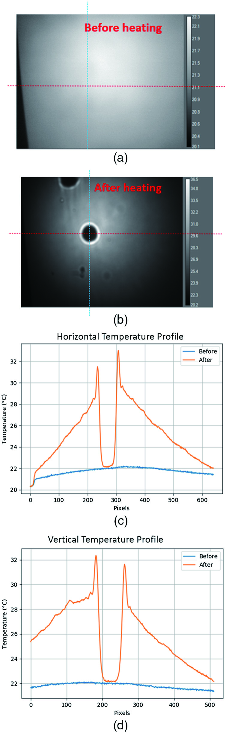 Fig. 11. Thermographic temperature monitoring on the surface of the sample: (a) and (b) Surface temperature condition before and after laser heating, (c) temperature variation in the section of red dotted line in horizontal direction, and (d) temperature variation in the section of blue dotted line in vertical direction.
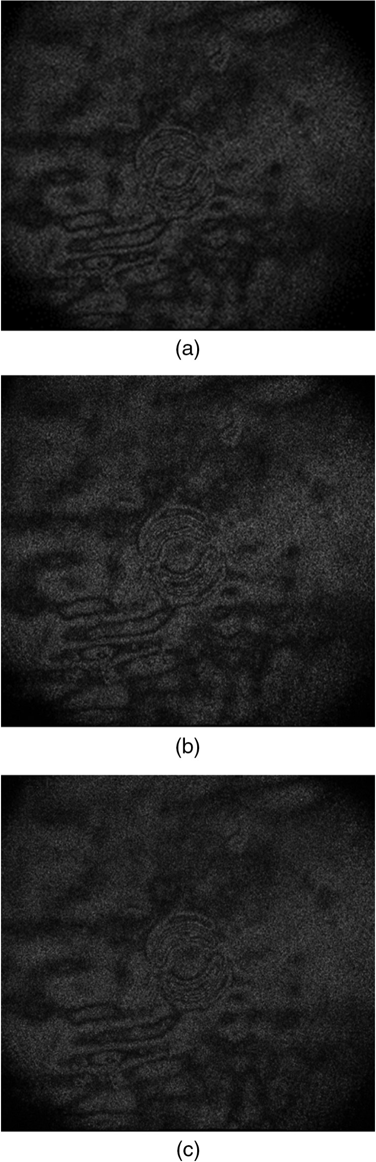 Fig. 12. (a) Shearography fringes using laser heating at 350 s, (b) shearography fringes using laser heating at 355 s, and (c) shearography fringes using laser heating at 360 s.
As can be seen in Fig. 12, subsurface defects and stress concentration could be seen from a certain area, and the development of the fringes was smooth with no air flow disruption.
VI.CONCLUSION
This paper has introduced a compact shearography system for NDE monitoring of WTBs. The experimental test has been carried out for its workability on a WTB surface. It could be concluded from the tests that the shearography system is able to inspect the subsurface defect on most of the WTB areas. However, for the area that the stiffness of the glass fibre is hard, the shearography system is yet to be tested for defect due to limitations of the loading method and undetectable environmental conditions. Furthermore, the robotic system used in the study can carry the shearography system for inspection. The suction cup powered by pneumatic system is for the elimination of the relative motion between shearography and the WTB surface. The post-processing results have indicated that the original fringes need to go through a smoothing procedure to derive a higher definition phase map. It has been demonstrated that the developed system is capable of fulfilling the task of inspecting the WTB without having to send a technician to the wind turbine tower. The paper has also discussed the availability of using laser heating as a more advanced loading method for further WTB on-site inspection. According to the results obtained, laser heating could be practically used in future WTB shearography inspection development for a deeper defect inspection within shorter inspection time.