I.INTRODUCTION
During the 1970s, the flexible pipeline technology began to be used initially in benign, shallow water conditions such as the Mediterranean. By the 1980s, the technology was developed and matured to the level that could be adopted by industry to provide access to fields in extreme environments. In 1984, it revolutionized the oil and gas industry when the flexible pipelines began to be used as risers in North Sea. Since then, the flexible pipes have been widely adopted for connecting floating equipment such as floating production, storage, and offloading to the seabed. The wide adoptability of flexible pipes was because of their inherent flexibility that enabled to overcome the challenges posed by dynamic environments [1]. These flexible pipes used as risers are to connect offshore platforms to subsea equipment for production and drilling purposes. These are capable of carrying a wide range of fluids such as hydrocarbons, gas lift, and injection and control fluids. The demand for flexible risers is continuously growing considering the benefits these offer as compared with fixed steel pipes. Currently the global market is equivalent to around 1,200 km/year of new pipe [2].
The flexible risers’ main advantage of being flexible is due to its construction that comprises of many layers [3] instead of single thick layer of steel as shown in Fig. 1. These layers are able to slip past each other, thereby imparting low bending stiffness characteristics. The design of each layer contributes to a specific function. The inner steel carcass provides protection against collapse of the liner under hydrostatic pressure and prevents fluid pressure leaking into the annulus. There is a polymer sheath around this that acts as the seal to prevent leakage of the bore fluid getting into the annulus. There are further a number of layers of steel wound armor; the pressure armor resists radial hoop stresses and the tensile armor that carries the weight of the riser by resisting axial tension. For high tension applications, further layers can be incorporated in the design. The outermost layer is made of polymer sheath that acts as a barrier to seawater but is susceptible to most accidental damages during transport, installation, and operation. All flexible pipes are designed based on the above concept that can have variations in terms of materials used and number of layers to cope with specific operating environments such as operating depth or operating temperatures.
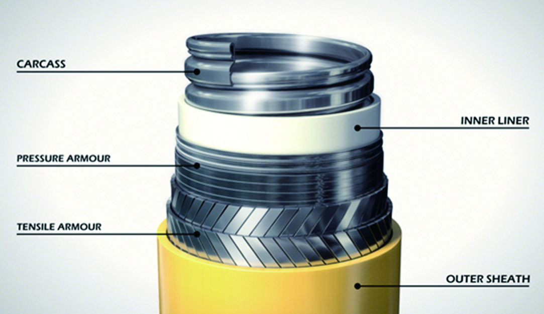 Fig. 1. Riser construction [4].
This paper presents the development of an automated inspection system for flexible risers that are used to connect wellheads on the seafloor to the offshore production and storage facility. The rest of this paper is organized as follows: Section II describes the most common flexible riser flaws and failure modes. Section III describes the prototype development of a robotic inspection system. Section IV describes system deployment for subsea flexible riser inspection. Section V presents conclusions and future work.
II.FLEXIBLE RISER FLAWS
The steel risers’ equipment life is about 25 years, and the same is expected life for flexible risers. However, it is quite difficult to achieve in flexible risers due to wide range of damages and failures that can occur as detailed in the American Petroleum Institute recommended practice guide [5], [6].
As mentioned earlier, the outermost layer of polymer sheath is most prone to damages. However, damage to the outer sheath sometimes leads to damage in internal layers such as corrosion caused by water getting into internal layers. External sheath damages can happen while transporting the risers, installations in the oil fields, or during operation and in-service abrasion with other parts of the installation or with the age of the polymers [7]. Fig. 2 shows some examples of damaged risers.
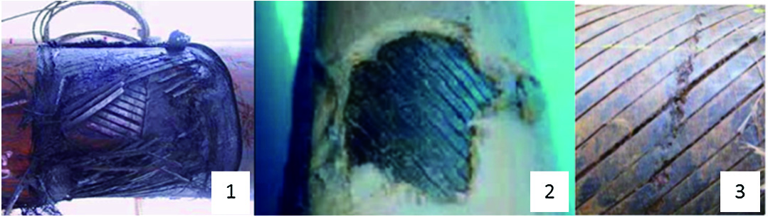 Fig. 2. Riser damage: (a) armor wire breakage, (b) external sheath damage, and (3) armor corrosion.
Various research- and industry-based studies are being carried out to get understanding of the mechanisms that result in flexible risers’ degradation and failures. The examples of these studies include the Petroleum Safety Authority study that was commissioned in 2014 to understand degrading mechanism of flexible risers, the failure modes, inspection, and integrity management [8]. A Norwegian study was carried out with similar focus, and the data indicate of at least a 1.5% probability of riser failure for each year in service. A detailed literature review on failures in pipelines and risers is presented in [9]. Due to these failures, very few flexible risers have met their service life indicated by their design.
An integrity management is a continuous assessment process applied throughout design, construction, installation, operation, and decommissioning phases of an infrastructure that is equally applicable to flexible risers. This is to ensure the asset is managed safely during their life cycle. For in-service integrity of the subsea equipment, the Det Norske Veritas (DNV) standards require that design intent is maintained, and the information about any degradations in the structural integrity of the risers due to the operational environments is available [10]. The standards also mention guidelines to carry out periodic asset inspection and assessment to have knowledge about degradation.
A wide range of nondestructive testing (NDT) methods are available for inspection of flexible risers but can be used to inspect only certain parts in certain conditions. Radiography is the only method that can do the volumetric inspection and can inspect all layers in one go. However, traditional radiography using phosphor plates or wet films has been used very limitedly because of its impracticality of use in the subsea environment and time consuming nature of executing the inspection process. The process involves exposure of the radiography detection media to capture images of internal layers of the riser and then taking the media to topside where the images are developed and processed [11], [12]. The application of digital radiography (DR), whereby a marinized underwater flat panel detector is deployed as the radiography detection media, has been previously researched and demonstrated in [13] and [14]. Another robotic DR is a method that allows faster acquisition of radiographic images. The imaging data in digital format can easily be transferred to the topside using the data communication methods and can be processed digitally using computing power of computers and further algorithms can be applied to analyze the data quickly. This way, it is much more efficient than the traditional radiography methods. However, to uptake the use of DR in the oil and gas industry, the deployment methods for DR needs to be developed for automated inspection of risers in service.
III.DEVELOPMENT OF RISERSURE ROBOTIC SCANNING SYSTEM FOR DEPLOYMENT OF RADIOGRAPHY
Under EU funded project “RiserSure,” a robotic system for deployment of radiography-based NDT system has been developed for subsea environment. The aim of the robotic system is to provide in-situ inspection of the flexible risers without removing these from their installations and carrying out the inspection in service. Risers’ operational capacity is expected to be 25 or more years in the oil fields by their design and to ensure their integrity during their lifetime, regular NDT inspections are required. Removing these from service for inspection is prohibitively expensive and can result in further damages or failures during the removal process, RiserSure must be able to carry out in-service inspection and provide the inspection data remotely. Conventionally, the in-service inspection is carried out either by divers or remotely operated vehicles (ROVs). There are associated operational risks in intervention by a diver, especially in the case of radiography inspection it is not easy as the inspection units are relatively heavy compared with other inspection techniques. The radiography source and detector need to be aligned directly opposite to each other and need to be moved very precisely at considerable low speeds to have enough exposure time to capture the images. The interventions using ROV are very expensive and face similar problems as with diver based inspection using radiography method due to its specific requirements.
RiserSure has developed two robotic scanner systems capable of subsea operation to 100-m depths. The critical area for riser damage and failure is from the splash zone, and the submerged zone just below mean low water level, down to around 50 m where there is a high risk of mechanical damage and high oxygen levels that accelerate corrosion of damaged riser [15], [16]. The first prototype design does not need either divers or ROVs for deployment. The robot capsule is connected to the riser near a topside hang-off point and winched down the riser (as shown in Fig. 3). This allows inspection in the critical areas where riser damage often occurs; the splash zone down to 50–100 m below the surface. The first prototype system has been developed to establish the scanner system suitability for radiography operation underwater. Once the radiography images in shallow water are obtained during the trials and the required performance established, the second prototype is developed to enhance the automation and increase safety of the system with an automated holding mechanism and encapsulation of the system in a roll cage (subsea industry requirement). In addition to these, the second prototype has been developed to incorporate ROV deployment as well.
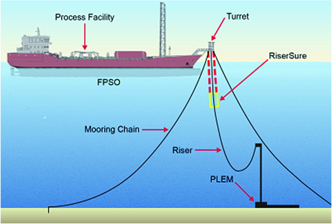 Fig. 3. Typical deployment strategy for the RiserSure capsule.
The main operational requirements of the robotic system have been driven by the NDT payload that consists of radiography source and detector and functional and performance requirements around that. The robotic system needs to carry the radiography units to the point of interest, to securely hold its position around the riser and scan around the riser for complete 360°. The system must be able to operate at different scanning speeds depending on the exposure time required for a particular riser. The system has been designed around the requirement to scan the flexible risers with diameters up to 250 mm considering that the majority of risers are of around this size or less in the North Sea [7]. To build up a detailed radiographic image that will capture small defects, the rotational speed of the drive system on which the radiography units are mounted and moved is very low (0.03 rpm) and precisely controlled [17], [18].
The core of the prototype robotic system is an open platform that can be positioned around a riser with very little or no manual adjustment. The only part of the capsule that needs to be opened to encircle a riser is a two-piece precision rotary ring gear that is used to carry the radiography units and move the units with required precision. This design approach is chosen to make the system easily adaptable in case the deployment through ROV is required. The rotary ring is actuated by a subsea motor driven pinion gear and floats on three thrust bearings fixed permanently on a base plate, capable of carrying the payload of NDT units at required speed. A 3-D model of the prototype is shown in Fig. 4. A gripper system consisting of linear slides has been incorporated that holds the riser during scanning inspection. The mechanism keeps the radiography units stable against wave disturbances while scanning to take radiography images and to avoid collisions with the riser surface. The system has been designed to work down to 100-m depth in subsea environment.
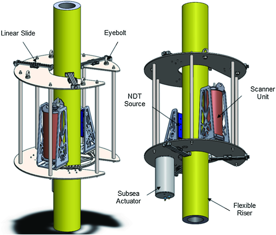 Fig. 4. 3-D model of the first prototype of the robotic scanner system.
A second prototype of the scanner system was developed to automate the holding of the riser and enable ROV deployment along with the winching system. The incorporation of an ROV deployment capability required major changes to the design. The problem was how to assemble or close the ring comprising of two 270° and 90° segments. This was solved by driving the 270° segment of the ring (with gamma ray source and digital detector mounted on it) with two pinion gears rotating them by 360°. To balance the load on the ring, the ring was floated on seven bearings mounted on the base plate and one additional bearing mounted on the roll-cage door. Closing the roll cage door results in the ring floated on eight bearings which allows the ring to complete a full circular motion.
The 3-D model and the actual mechanical hardware of the developed system are shown in Figs. 5 and 6, respectively.
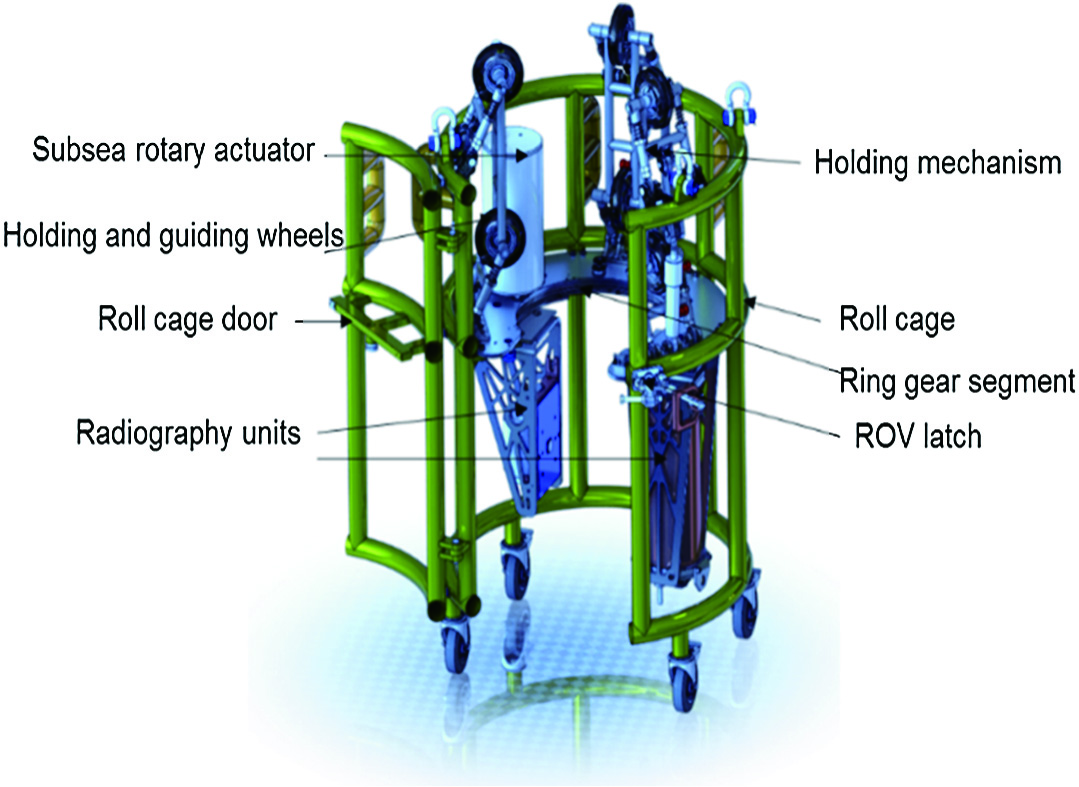 Fig. 5. 3-D model of the mechanical assembly prototype II.
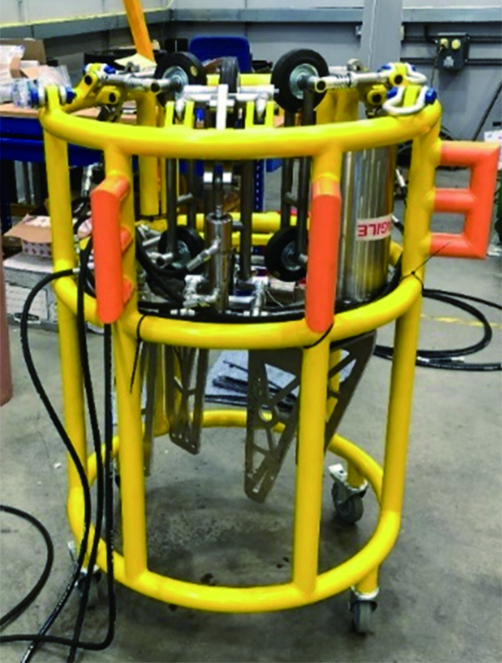 Fig. 6. Actual mechanical assembly of the developed system.
The RiserSure scanning system has been implemented using bespoke subsea actuator, built with its on-board drive and control circuitry within the subsea enclosure that can operate to 100-m depths underwater. The actuator includes its internal encoder for position feedback, having current limit control, internal temperature, and status monitoring registers. The low-level controls to react to the control commands are performed in the on-board controllers while the supervisory control of the complete system is implemented and executed on a dedicated industrial computer. The gripping system due to power required to hold has been implemented around hydraulic cylinders and controlled through electrical interface connected to topside controller. This enables the scanner system to be controlled remotely from the topside. All the robotic subsea units are connected to the topside unit using the controller area network (CAN) bus. The actuator acts as a node with its own unique ID.
Due to the high costs involved in the fabrication of subsea equipment and specifically enclosures, the control hardware of the robotic system has been configured by integrating dedicated in-built controllers and drive electronics, creating networked control system using CAN bus that needs two differential lines for communication and by using splice extensions of the subsea umbilical to reduce the number of units that need to be enclosed.
The configuration of the robotic system, consisting of robotic control hardware, interfaces, and the radiographic electronics modules, is shown in Fig. 7. The inspection detector consists of an in-built read-out and processing circuitry that senses the received X-rays at its surface and converts into electrical signals. The array detector outputs are preprocessed, digitized, and transferred to the topside dedicated computer using Ethernet communication and processed using dedicated software package. The digital detector has a separate DC power supply and controller, which is supplied with the system. The source controller unit contains the pneumatic/hydraulic supply and valve system, which controls the subsea source unit to open or close the shutter for exposure.
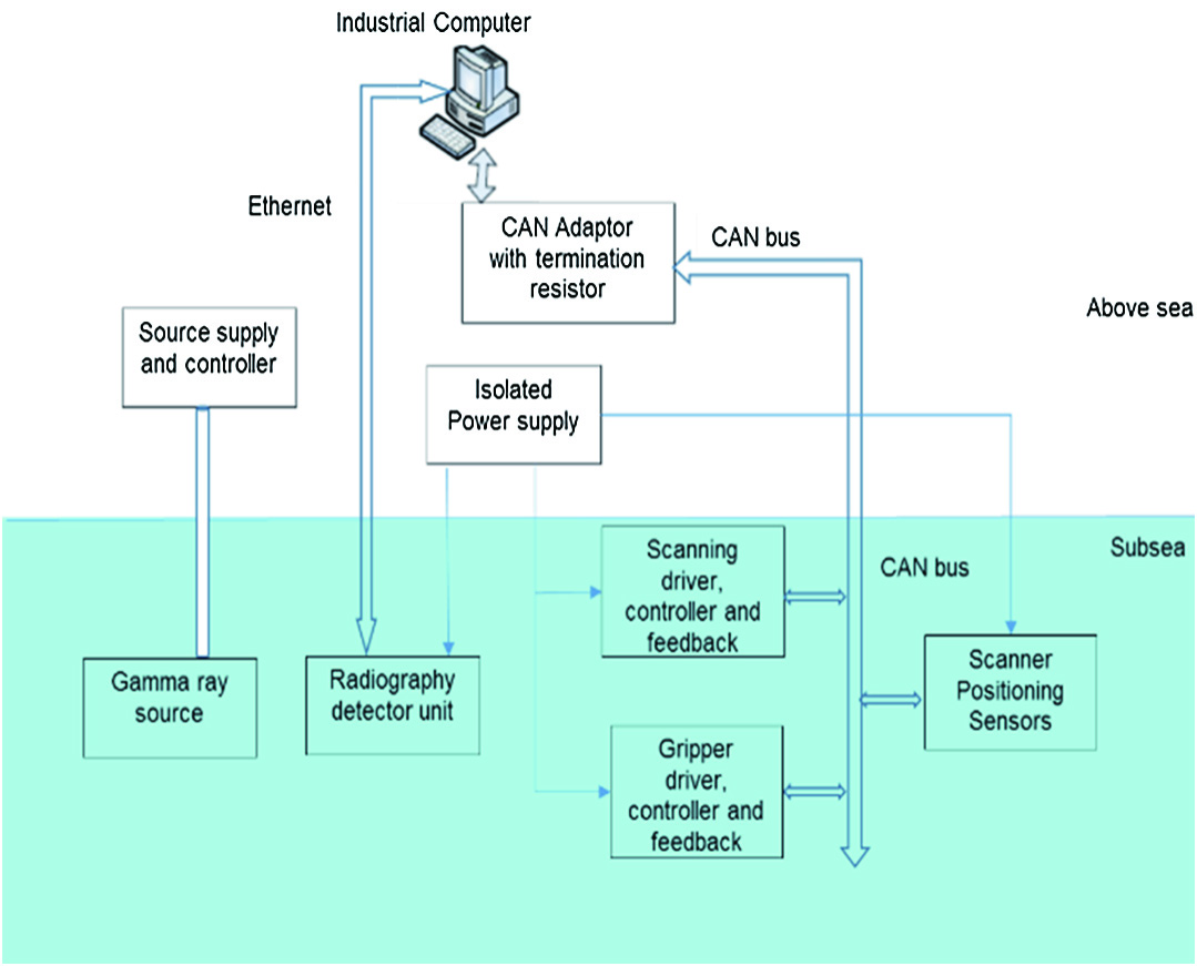 Fig. 7. System configuration of the robotic control hardware.
A graphical user interface-based supervisory controller is developed that includes the control of system operational modes based on user inputs and internal system parameters. It monitors critical operational and motion parameters of subsea units, displays the system status and warns about system errors. The guidelines from subsea standards are implemented in the control software. This consists of the timing parameters for sampling of inputs, display updating rate, continuous position monitoring of the robotic system, display of modes being executed, checks on user inputs, provision for stopping execution for any of the operational modes, and saving of data as required.
Implementation of control software for the above functionality considers requirements for DNV standard (DNVGL-RU-UWT-Pt5Ch9-1.4) [19] and safety measures to conform to machinery directive. Accordingly, provisions have been made for the following in the controller software for the system to be:
- •able to monitor the position of subsea system at any time,
- •monitor actual status of subsea system and the function in execution,
- •display operating parameters required for safe operation and providing alarms, and
- •able to stop execution during any of the operational modes.
The data flow diagram for the control software, as depicted in Fig. 8, shows the various components of the software and interfaces for data with hardware elements in the system.
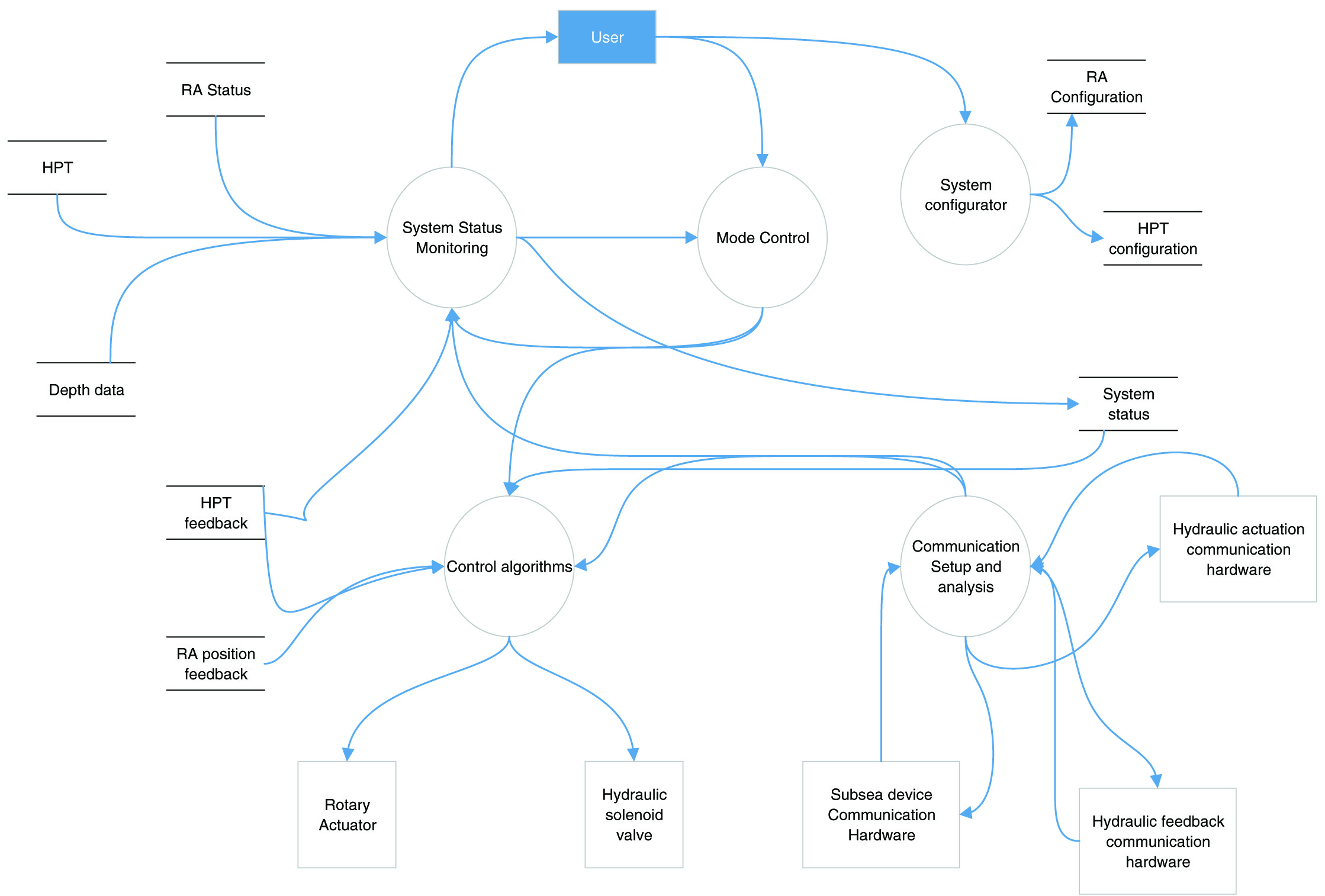 Fig. 8. Data flow diagram for scanner control software.
To cater for various operational scenarios, the control software facilitates six different operational modes: hold, release, neutral, scan, homing, and safe. The hold, release, and neutral modes are associated with the holding mechanism for gripping the riser and releasing from it. In neutral mode, the wheels are not forced but touch the riser to help in moving along the riser vertically. The homing mode and scan mode need the system to be in hold mode as a precondition, otherwise it initiates a warning message to the user. In the scan mode, the scanner rotates the radiography source and detector 360° around the riser to carry out the radiography. The homing mode is a supportive mode to establish the zero position for scanning and to bring back the NDT units to an initial position. A special mode, that is, safe mode, is implemented to bring the radiography source toward the opening door in case of emergency so that it can be removed from the capsule.
Fig. 9 shows the main screen for control operations and status updating of the control components. The topside buttons (in green) can be used to command the system to operate in the respective modes. The current mode of operation is indicated during the run time in the center indicator box (shown blank in the captured snapshot).
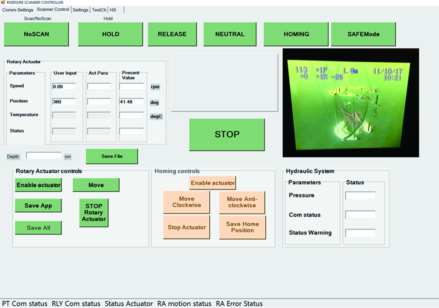 Fig. 9. Scanner control software interface screen.
The control software has features that continuously save the updated position in the configuration file at a rate of 1 Hz, and in case of any unexpected shutdown, on restarting the software, the last saved position is read in for user to know the current position of the system.
The hardware and software of the robotic system are based on a modular structure that facilitates easy integration of additional hardware units in the system and respective software components.
The winch system to lower and raise the capsule is a subsea certified commercially available system which is operated independently. However, for safety purposes, before the execution of any operational modes, except the emergency stop, the user is required to confirm the operation, allowing the verification of external and internal system conditions. To resist the subsea environment and to withstand the environmental loading, all the mechanical parts and enclosures are manufactured from stainless steel.
IV.ROBOTIC SCANNING SYSTEM DEPLOYMENT FOR SUBSEA FLEXIBLE RISER INSPECTION
The developed robotic system for RiserSure is subjected to several laboratory based trials before taking it for sea trials to test and demonstrate that the system has the capability to transition to seawater operation. The shallow water trials (<10-m depth) are performed at the seawater-fed Loch Linnhe in Fort William, Scotland [20]. The RiserSure system is deployed across the flexible riser sample on the surface and then lowered into the water. The functioning of the system is controlled from a control room on the surface where NDT and robotic supervisory control hardware and software are installed. The surface level systems are connected to the underwater units through umbilical. The commands for movement at various speeds are given to allow the system to remotely image a full 360° section of the riser at different exposure times. A photograph of the submerged system is shown in Fig. 10, where the core functionality of the system was proven. Due to the shallow depth (<10 m) the source container could be pneumatically operated using compressed air. High quality, radiographic images of the riser were captured and tested for different exposures and varying scanning speeds. A key factor in obtaining a high quality radiographic image with the RiserSure system is the synchronization between the detector’s image acquisition speed and the rotational speed of the scanner module. For optimal operation, the radiography detector required to acquire a line of the image each time the object moved a distance equal to the detector’s pixel width (assuming no geometric magnification of the radiographic image). If the detector acquires the line images too fast then the resultant radiograph becomes stretched, a too slow acquisition results in a compressed image, which could lead to image blur and small defects being masked and undetectable.
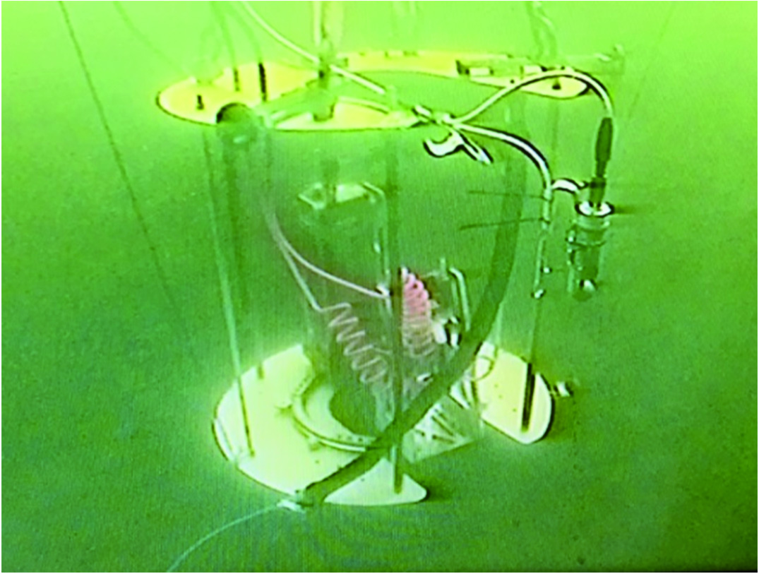 Fig. 10. Robotic inspection system winched underwater ready to be inserted around a riser by an ROV.
Fig. 11 shows a radiographic image for a 360° scan of the riser. The images captured the two impressions of artificially created defects in the acquired image. One defect is proportional in size at low magnification when the detector passes the defect side, and the other is a highly magnified but distorted version where the Gamma source passes the defect side.
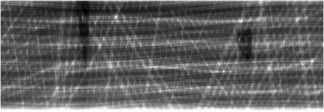 Fig. 11. Radiographic image showing 360° scan.
The results achieved during trials captured the images of the internal structure of the flexible riser sample. It proved the suitability of the robotic inspection system to carry out the radiographic inspection of flexible risers. The tests are repeated at different speeds and at different positions and proved that with the developed robotic system, high quality radiography images of the internal structure of the riser can be achieved.
Once the concept with RiserSure prototype I was proven, prototype II was developed and was field trialed at deeper levels up to 23 m. The deployment was carried out with ATEX approved winching system to lower the scanner system underwater and then taken over by ROV deployment to encircle around the flexible riser. Figs. 12 and 13 show the deployment using winching system to lower down the scanner system underwater at The Underwater Trials Centre, Fort William.
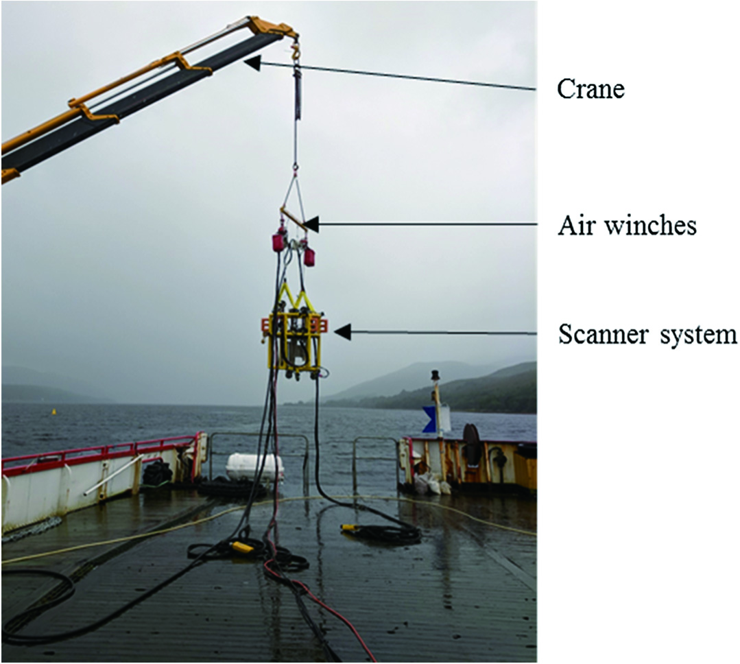 Fig. 12. System preparation for lowering into the sea.
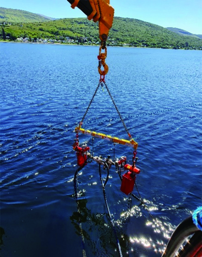 Fig. 13. System deployed underwater with air winches above water.
Once the system was at testing depth around 23 m, the work class ROV took over. The door for entering to grab flexible riser was opened by one arm of the ROV while holding the system with the other arm. It moved the system to a central position around the riser. At this point, the system was operated in the hold position to grab the riser. Once hold was accomplished, the system was supported by the winching system, and the ROV was moved to the front side of the roll cage to close the door.
Figs. 14, 15, and 16 demonstrate the deployment underwater with ROV. The images were captured by an observation class ROV which was also lowered underwater along with the system.
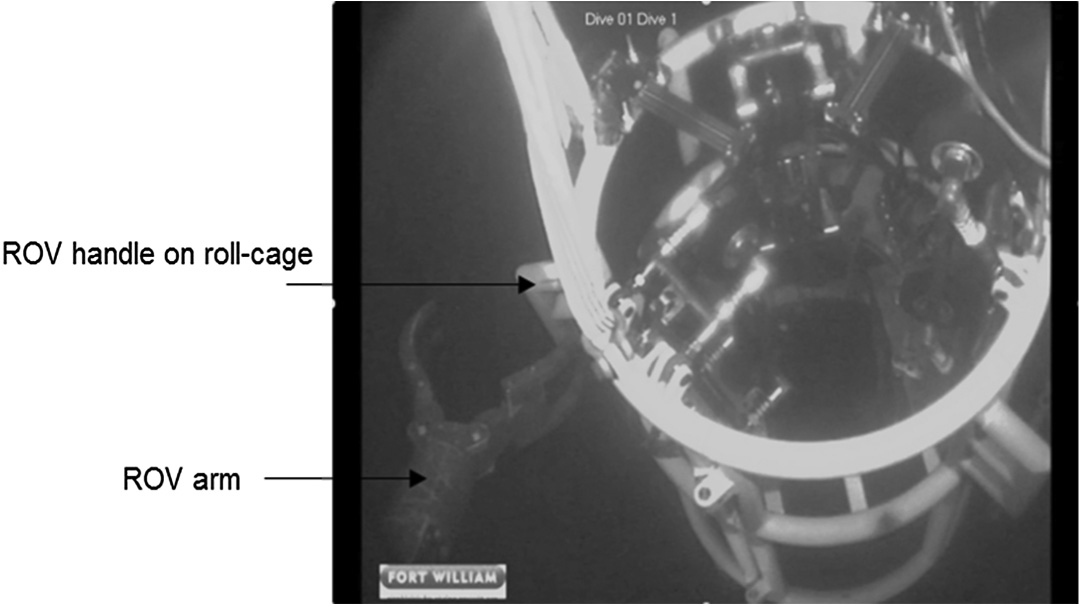 Fig. 14. ROV arm grabbing the scanner system by holding onto ROV handle on roll cage.
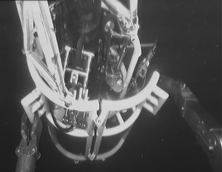 Fig. 15. System put around the riser, held by the scanner system and ROV closing the door.
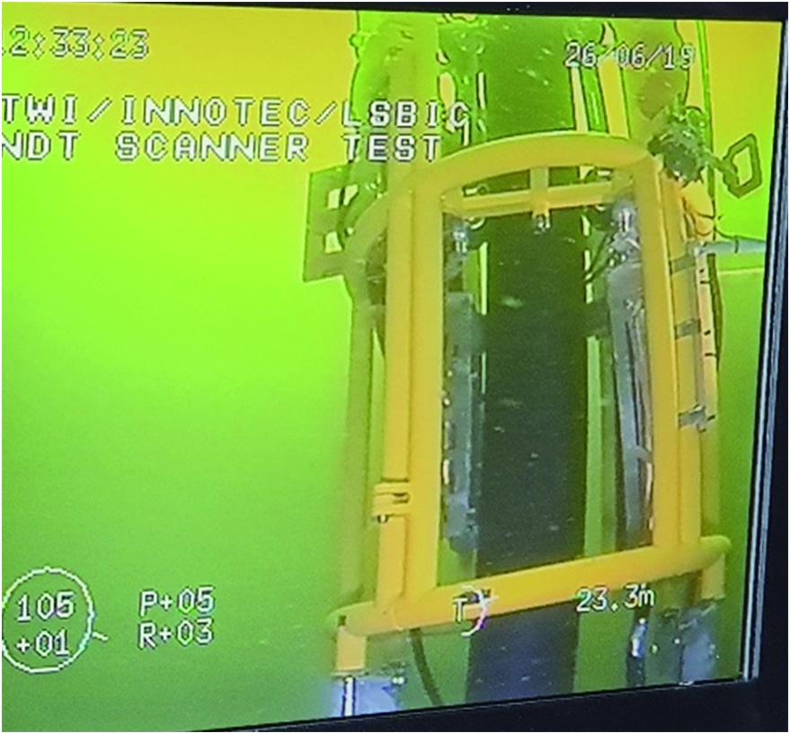 Fig. 16. System placed completely around the riser and performing 360° scanning.
In this set of trials, scanner system deployment with a winching system and in combination with an ROV was successfully established.
V.CONCLUSIONS
For NDT of multilayered flexible risers, the radiography method provides an excellent inspection method. The development of subsea automation to deploy radiography NDT presents challenges as the requirements are for a robotic system with high payload capacity, precise rotational position, and speed control and subsea operation. The high payload is due to the weight of the NDT units which are enclosed in thick-walled stainless steel enclosures required for subsea operation to depths of 100 m. Scanning precision is required to move the source and detector in alignment and at low speeds to meet required exposure times. Two robot prototypes have been developed. The first prototype, deployed with a winching system, has successfully demonstrated the feasibility of using a robotic scanner system by achieving high resolution radiography images. The second prototype has been developed for enhanced automation, safety, and deployment by an ROV. Field trials of the second prototype have demonstrated successful deployment using a combination of winching system and ROV that enables the system to work underwater as well as above water. Further advanced technologies can be incorporated to enhance the system capability by having on-board cameras to observe movement around the riser and to possibly carry out visual inspection at the same time.