I.INTRODUCTION
By conducting planetary explorations, we can explore not only the origins of the planets but also the source of life. Because of that, many missions for exploring the planets have proceeded. Hayabusa2 landed on a surface of an asteroid Ryugu and took the sample in 2019 [1]. It returned the sample to Earth. The Mars Perseverance rover successfully landed on Mars in February 2021 [2]. It will collect samples of rocks and soils. Moreover, concern with the Moon has been growing. In recent years, many missions for exploring the Moon have also proceeded. For example, there are launching Smart Lander for Investigating Moon (SLIM) and developing Gateway, which is a platform orbiting the Moon [3,4]. Therefore, these conditions will make many opportunities for exploring robots to land on the surface of the Moon.
In planetary explorations, exploring robots that are called rovers were used and obtained various knowledge [5]-[7]. Rovers explored planets by moving on surfaces of them. Many rovers were vehicle type, which consisted of wheels [8,9]. However, the running performance of the wheel-typed rovers is not good. In recent years, the legged robots are focused on as exploration rovers with high running performance [10]-[13]. The legged rovers are good at moving on rough terrain which is rocky. Viking 1 and 2 that were the probes and explored Mars observed the geographical features of Mars. According to the observation results, there were many rocks that were larger than 30 cm on the ground [14]. Therefore, the running performance on rough terrain is important for exploration rovers.
The grounds of Mars and the Moon are not only the rough terrain but also the loose ground. The loose ground is covered with the loose soil called regolith and is easy to deform by receiving external force. Moreover, there are many craters on Mars and the Moon. These craters have slopes. From these features of the loose ground, there are two problems. First, legged rovers slip on the loose ground. The loose ground is easy to deform by the motion of their legs. Some studies address this problem. Yeomans et al. considered that the earth pressure that gives to the legs of rovers is the traction force of legged rovers [15]. They measured the earth pressure in the experiment and proposed the model of the earth pressure for legged rovers. As a result, the earth pressure was strongly dependent on the amount of leg subsidence. The higher the amount of leg subsidence was, the larger the earth pressure was. Therefore, legged rovers can prevent slipping on the loose ground by increasing leg subsidence. Moreover, our study group was confirmed that there are two effects when the loose ground is given vibration [16]. One was to increase the density of the loose ground, and the other was to increase the leg subsidence. The walking method that prevents slipping the rover on the loose ground was proposed using these effects. In the experimental results, the amount of movement using the proposed walking method became longer compared with one without vibration. Then, it is the problem that legged rovers fall down by deforming the loose ground. The posture of the rovers is easy to change on the loose ground. Some studies address this problem. Komizunai et al. constructed the simulator about a humanoid walks on the loose ground [17]. In this simulator, the amount of leg subsidence when walking was estimated. By estimating the amount of leg subsidence, the posture of a humanoid can be changed before it falls down. Kamegawa et al. proposed the method that the slope angle of the ground is estimated from the positions of rover’s toes and the posture of rovers [18]. Moreover, the gait was changed according to the estimated slope angle of the ground. Shirai et al. proposed the walking method that legs move preventing a fall of a rover based on tumble stability margin [19]. The effectiveness of this walking method was confirmed from the experiment. However, it is needed to move legs to stabilize the posture of rovers in these methods. Therefore, these methods cannot be used when legs cannot move by the structural restrictions of rovers. Nagaoka et al. developed the gripper that gripped a rock for legged rovers [20]. In this study, a legged rover could walk by using this gripper without falling. However, this gripper is not effective in the loose ground because the loose ground is easy to deform by receiving external force.
This study addresses the problem that legged rovers fall down on the loose ground with a slope. Moreover, the walking method that prevents a fall of a legged rover is proposed. In the proposed walking method, legs are sunk by giving vibration to the loose ground. The posture of legged rovers is changed to prevent to a fall of it by sinking legs. The posture of legged rovers can be changed without the structural restrictions of them because the proposed walking method uses changing shape of the loose ground.
In the rest of the paper, a walking method to prevent a fall of a legged rover using vibration is proposed in Section II. In Section III, the relationship between the kind of vibration and the leg subsidence is confirmed. Sinking legs by giving vibration is important because the posture of legged rovers is changed by sinking legs in the proposed walking method. Then, the legged testbed walks on the loose ground with a slope using the proposed walking method. In this experiment, the effectiveness of the proposed walking method is confirmed. This experiment is reported in Section IV. Finally, this study is concluded in Section V.
This study’s contribution to knowledge is shown below:
- •Feature of resistance force that rover’s leg is received from the ground in vibrating.
- •How to use vibration for walking method that prevents a fall of the planetary exploration legged rover?
- •Effect of a walking method to prevent a fall of a legged rover using vibration.
II.PROPOSAL OF WALKING METHOD TO PREVENT A FALL OF A LEGGED ROVER USING VIBRATION
A.MECHANISM THAT ROVER FALLS DOWN ON THE LOOSE GROUND WITH A SLOPE
In this section, the necessity of a walking method that prevents a fall of a legged rover is explained. First, the mechanism that a rover falls down on the loose ground with a slope is explained. In this study, the moment that is generated by the weight of a rover on a slope is called Mos (moment on a slope). The illustration of the forces that a rover is received on the loose ground with a slope is shown in Fig. 1. Fig. 1 shows the simple forces in a two-dimensional coordinate system. In Fig. 1, Mos is caused around PR (the touching point between the ground and a rear leg). The term Mos is calculated from (1)
where m is the mass of a rover, g is the gravitational acceleration, ly is the distance from a rear leg to the center of gravity in a y-axis direction, lz is the distance from a rear leg to the center of gravity in a z-axis direction, and θR is the angle of a rover’s posture and calculated from (2)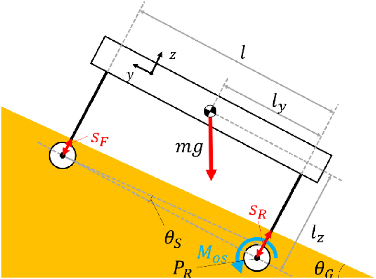 Fig. 1. Conceptual diagram of the moment on a slope.
where θG is the slope angle of the ground and θS is the angle of a rover’s posture, which is generated by the leg subsidence and calculated from (3)
where l is the distance from a rear leg to a front leg, sF is the subsidence of a rover’s front leg, and sR is the subsidence of a rover’s rear leg. The risk that a rover falls down is high when the value of Mos is small. Moreover, a rover falls down when Mos is less than 0.The reason that legged rovers are easy to fall on the loose ground is explained here. The term lz is large because the centers of gravity of legged rovers are higher than that of rovers using other moving mechanisms. Moreover, the loose ground is easy to deform by receiving external force. On the slope, sR is larger than sF because the weight of a rover that a rear leg is received is larger than one that front a leg is received. Therefore, θs is increased on the slope ( eq. (3)). The term Mos is decreased by increasing these values. The risk that a rover falls down is increased by decreasing Mos. Therefore, a walking method is needed, which prevents a fall of a legged rover.
B.PROPOSED WALKING METHOD USING VIBRATION
In this section, a walking method that prevents a fall of a legged rover is explained. It is needed to increase Mos by inclining forward a rover to prevent a fall of it. In the proposed walking method, Mos is increased using the feature, which is caused by giving vibration to the loose ground. The particles of the ground are moved by giving vibration to the ground as shown in Fig. 2. The shear strength of the ground is decreased by moving the particles. The amount of leg subsidence is increased by decreasing the shear strength. Therefore, a rover inclines forward by giving vibration to the ground.
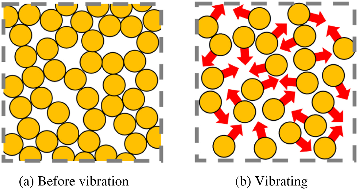 Fig. 2. Movement particles of the ground when vibration is given to the ground.
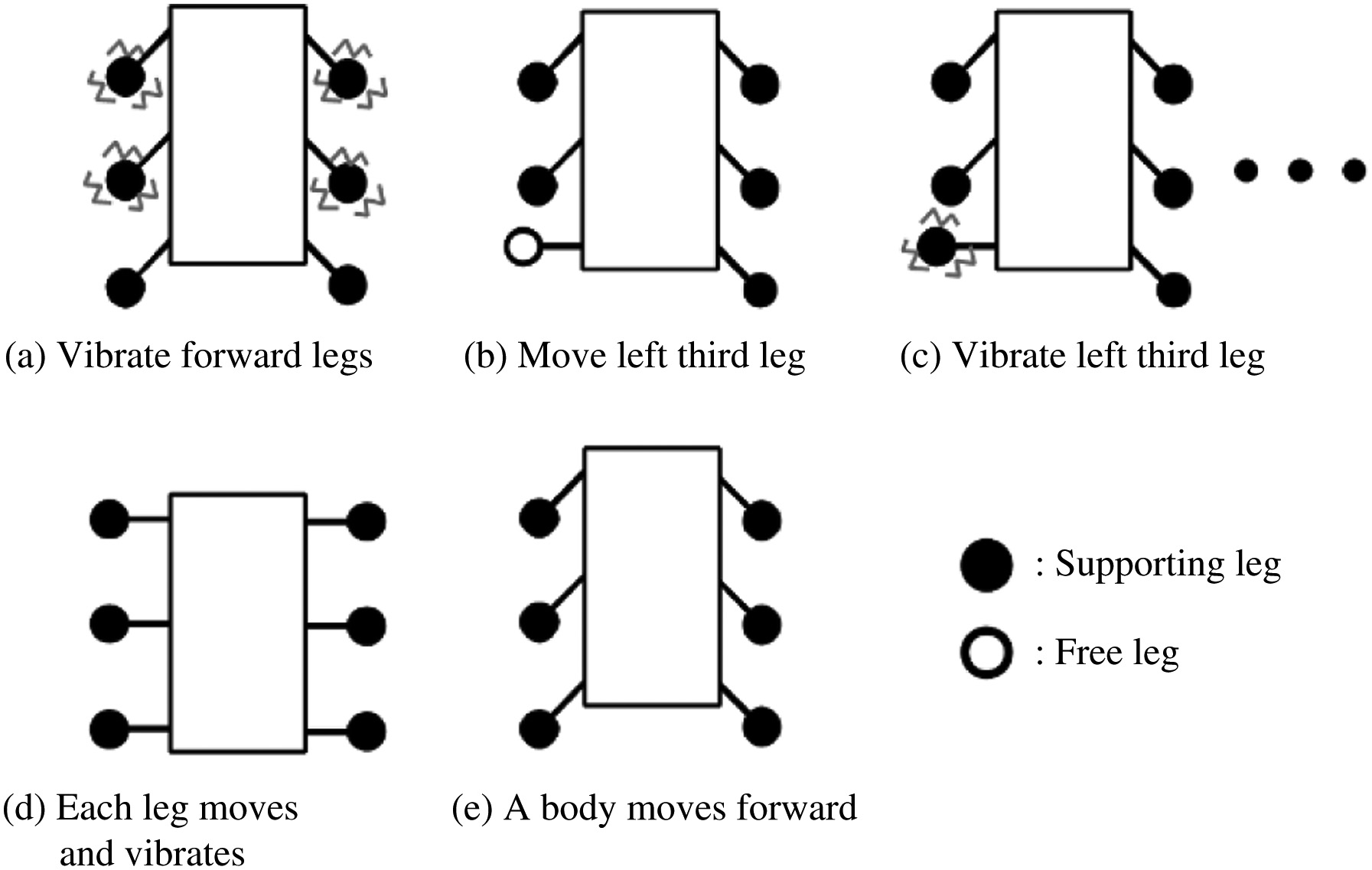
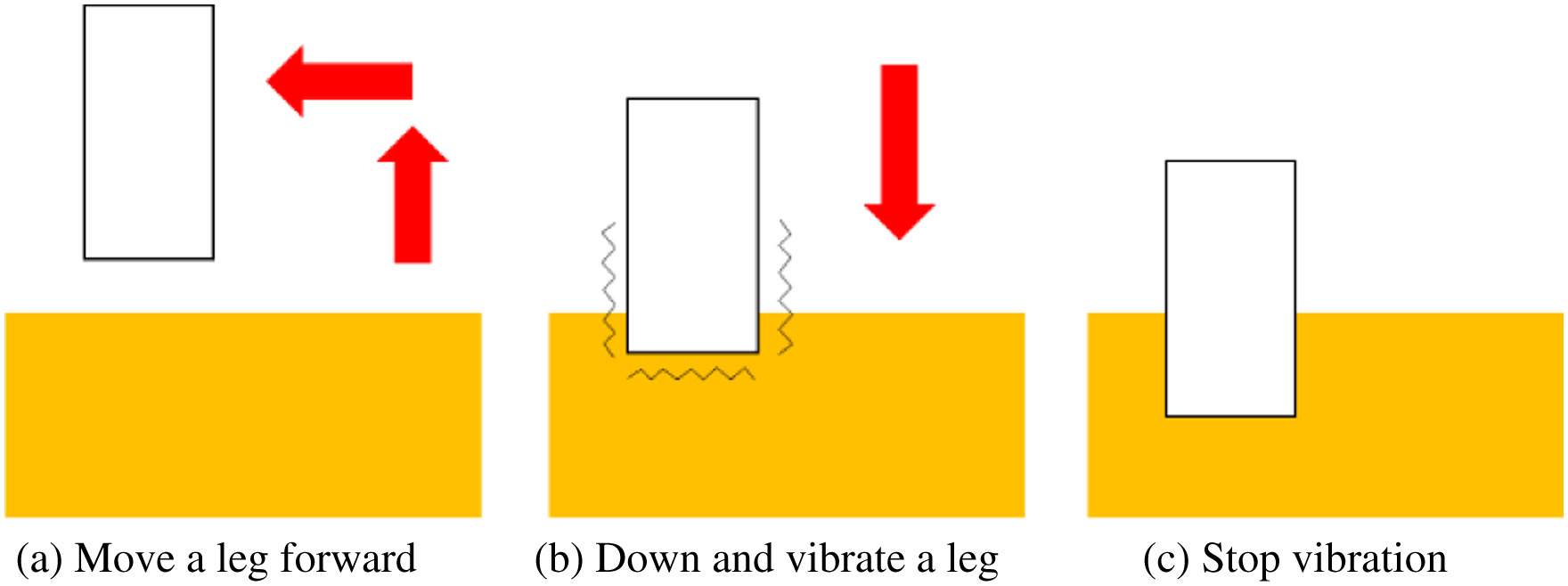
Details of the proposed walking method are explained. The proposed walking method is used for the six-legged rover. The reason is that the six-legged rovers can walk in static walking without moving the center of gravity. The proposed walking method is shown in Fig. 3. First, the front legs and the middle legs vibrate (Fig. 3(a)). The rover inclines forward by this motion. Then, the rover moves legs forward one by one (Figs. 3(b)-(d)). This motion is based on wave gait. Fig. 4 shows the movement of each leg and the timing to vibrate the leg. First, the leg raises and moves forward (Fig. 4(a)). Second, the leg moves down to the ground. Then, the leg is vibrating when the leg touches the ground (Fig. 4(b)). Moreover, the leg sinks into the ground. Finally, vibration stops when the leg finishes sinking into the ground (Fig. 4(c)). In the previous study, our study group proposed this motion as the walking method that the legged rover can prevent slipping on the loose ground [16]. This motion indicates that density of the ground and earth pressure are increased. Therefore, the traction force of the legged rover is increased by increasing earth pressure. The effectiveness of this motion was confirmed. Finally, the body of the rover moves forward (Fig. 3(e)). Moreover, one cycle of this gait is finished.
III.A PENETRATION EXPERIMENT FOR MEASURING RESISTANCE FORCE FROM THE GROUND
The relationship between the kind of vibration and the leg subsidence is confirmed. The smaller the resistance force which is received from the ground is, the easier the leg sinks to the ground. In this experiment, the rod is penetrated in the loose ground. Moreover, the resistance force that rod is received from the ground is measured. In this section, the experimental machine, the experimental method, and the result are reported.
A.METHOD OF A PENETRATION EXPERIMENT
First, the experimental machine is explained. The experimental machine is shown in Fig. 5. It consists of the soil tank part, the leg part, and the actuator part. The size of the soil tank is H 300 mm × W 354 mm × L 609 mm. Fig. 6 shows the structure and the size of the rod. The vibration motor is mounted in the rod. Fig. 7 shows the movement of this machine. The leg part is penetrated in the soil tank part by the actuator part. The leg part consists of the force sensor and the rod. The resistance force from the ground when penetrating the rod is measured by the force sensor.
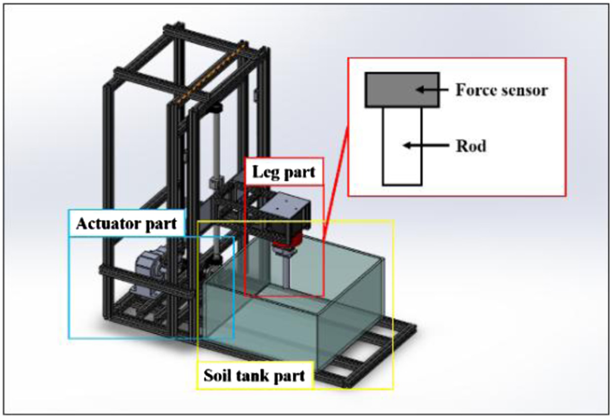 Fig. 5. Overview of penetration testing machine.
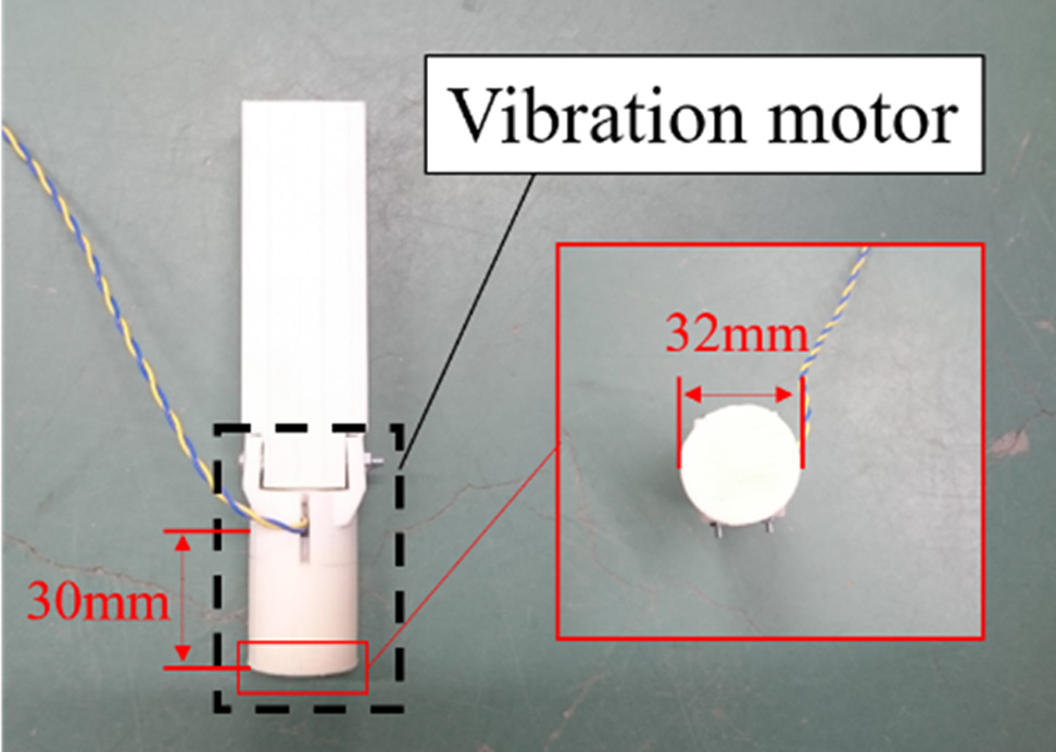
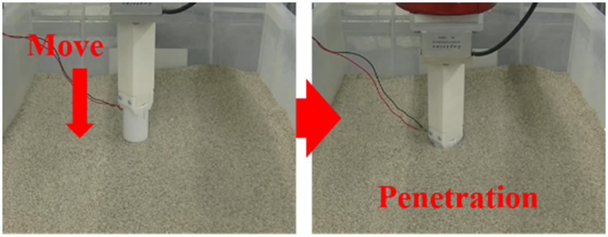 Fig. 7. Movement of penetration testing machine.
Then, the flow of the experimental method is explained. The flow of this experiment is shown in Fig. 8. The leg part is set on the ground (Fig. 8(a)). The ground consists of Silica No. 5. Then, the leg part is penetrated into the soil tank (Fig. 8(b)). The speed of moving the leg part is 0.55 mm/s. The vibrations are three kinds. These kinds of vibrations are prepared by changing the voltage that is supplied to the vibration motor. Table I shows these vibrations. The force sensor receives the value of the resistance force from the ground. The number of trials is 10 times. Table II shows the condition of this experiment.
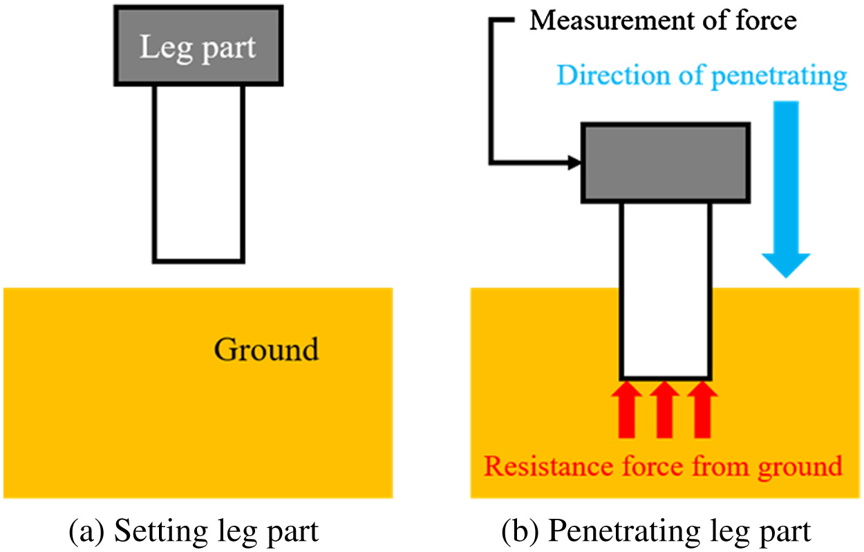 Fig. 8. Flow of penetration experiment.
TABLE I. Parameters of Table of Vibration
| Vibration | Supply voltage (V) | Vibratory force (N) | Frequency (Hz) |
|---|---|---|---|
| No vibratioon | 0 | 0.00 | 0 |
| Weak vibration | 10 | 0.27 | 70 |
| Middle vibration | 20 | 1.32 | 153 |
| Strong vibration | 30 | 3.04 | 231 |
TABLE II. Condition for Penetration Experiment
| Item | Conditions (value) |
|---|---|
| Number of trials | 10 |
| Penetration speed | 0.55 mm/s |
| Amount of subsidence | 50 mm |
| Kind of sand | Silica No. 5 |
| Vibration motor | TP-2528C-24 |
B.RESULTS AND DISCUSSION OF A PENETRATION EXPERIMENT
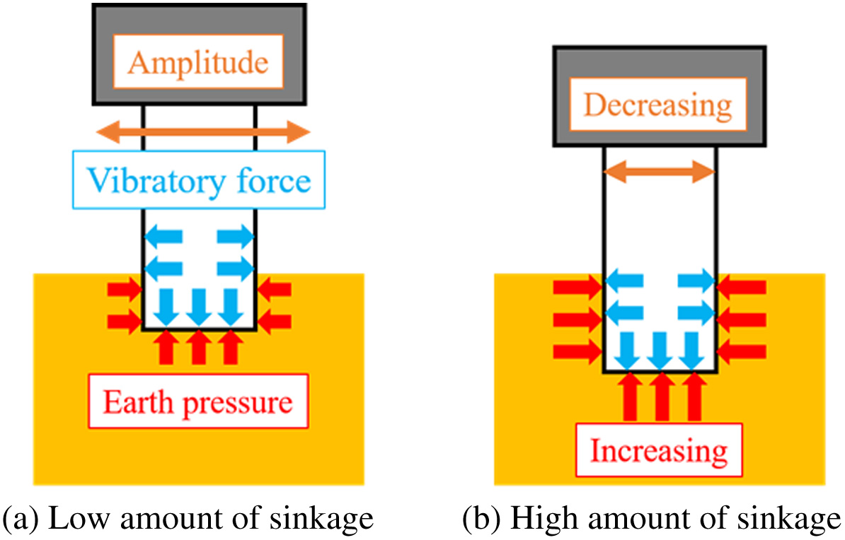
Figs. 9–12 show the graphs about the distance of subsidence vs resistance force from the ground in each kind of vibration. In Fig. 9, the resistance force was shown as a curve and increased in the experiment without vibration. From Fig. 9, these shapes of the graphs were hardly different in all trials. This minor difference in graph shapes is seemingly caused by the irregularity of the loose ground. As shown from Figs. 10 to 12, graph shapes in the experiment with vibration were different in comparison with that in the experiment without vibration. In the experimental results with vibration, the resistance force was low at the beginning of these graphs. In the same experimental condition, these shapes of the graphs were similar, but they have variations. The stronger the vibration was, the larger these variations were. These variations are seemingly caused by vibration given to the ground. The particles of the ground are moved by giving vibration to the ground. This movement of particles is irregular. Therefore, these variations are seemingly caused by moving the particles. In Fig. 13, the resistance forces are compared in each experimental condition of vibration. In Fig. 13, the data of median values are chosen because the resistance forces that were obtained in the same experimental conditions were hardly different in all trials. Fig. 14 shows the difference between the result in the case of using vibration and one in the case of not using vibration. At the beginning of this graph, the resistance forces in the case of using vibration were smaller than one in the case of not using vibration. In this result, the rod was easy to sink to the ground by giving vibration. Therefore, it is possible that the rover inclines forward by giving vibration to the ground. Moreover, the larger the vibratory force was, the smaller the resistance force was (Fig. 13). In this result, it is considered that the larger the vibratory force is, the more effective the proposed walking is. Finally, the resistance forces in the case of using vibration were increased rapidly and fit one in the case of not using vibration. The reason is considered that the higher the subsidence of the rod is, the larger the earth pressure is. The situation in each amount of subsidence is shown in Fig. 15. The amplitude of vibration is decreased by increasing the earth's pressure. Therefore, it is considered that the resistance force in the case of using vibration is matched with one in the case of not using vibration when the earth pressure is higher than the vibratory force.
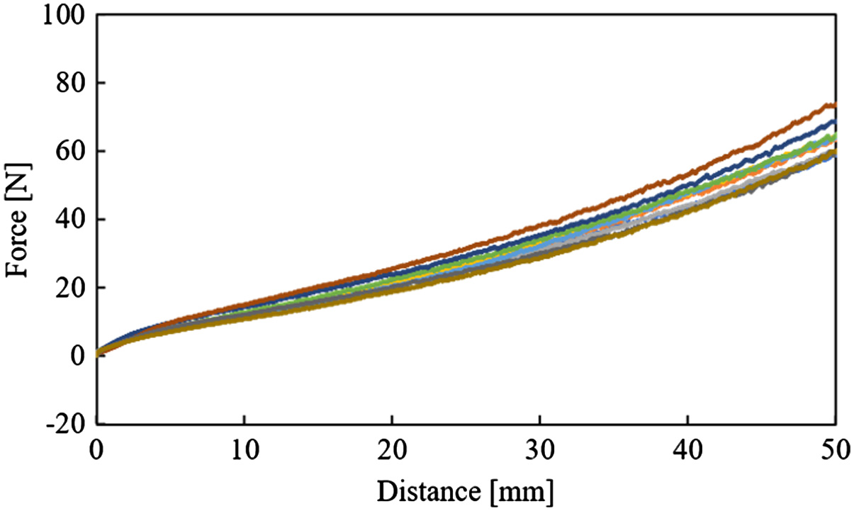 Fig. 9. Resistance force vs penetration distance using no vibration (vibratory force: 0.00 N and frequency: 0 Hz).
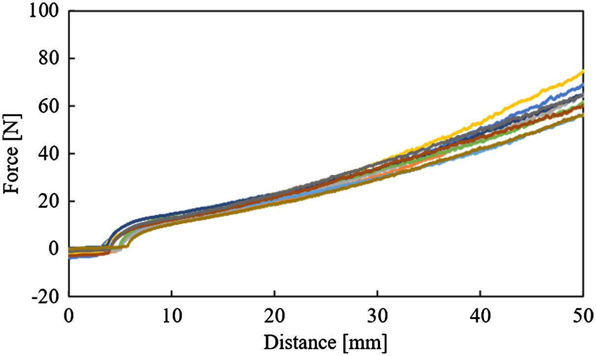 Fig. 10. Resistance force vs penetration distance using weak vibration (vibratory force: 0.27 N and frequency: 70 Hz).
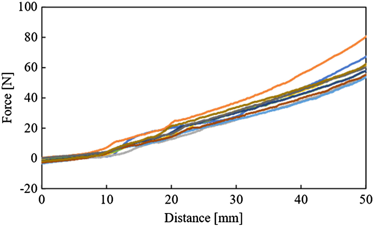 Fig. 11. Resistance force vs penetration distance using middle vibration (vibratory force: 1.32 N and frequency: 153 Hz).
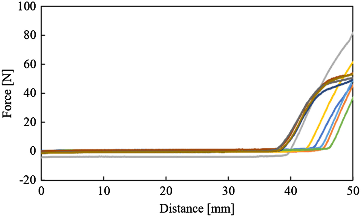 Fig. 12. Resistance force vs penetration distance using strong vibration (vibratory force: 3.04 N and frequency: 231 Hz).
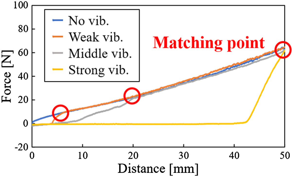 Fig. 13. Comparison of resistance force in each vibration.
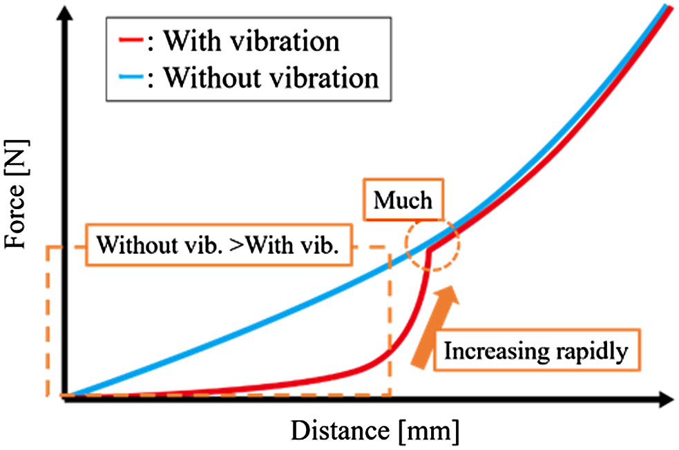 Fig. 14. Overview of difference between resistance force in the case of using vibration and one in the case of not using vibration.
IV.SLOPE WALKING EXPERIMENT FOR EVALUATING THE PROPOSED WALKING METHOD
The slope walking experiment is conducted to confirm the effectiveness of the proposed walking method. In this section, the experimental method, the testbed, the evaluation method of the walking methods, and the result are reported.
A.METHOD OF A SLOPE WALKING EXPERIMENT
First, the experimental method is explained. In this experiment, the testbed walks on the loose ground with a slope. The experimental environment is shown in Fig. 16. The ground consists of Silica No. 5. Two kinds of walking methods are used. There are the proposed walking and the walking without vibration. The proposed walking and the walking without vibration are wave gait. The entire walking motion is shown in Fig. 3. However, the motion that is shown in Fig. 3(a) is not conducted in the walking without vibration. Moreover, the details of these walking methods are shown in Fig. 17. In the proposed walking, the leg vibrates and sinks 30 mm to the ground after it touches the ground (Fig. 17(b)). In walking without vibration, this motion is not conducted after the leg touches the ground. Strong vibration is used in the proposed walking (Table I). The detail of the walking is shown in Table III. The slope of the ground changes by 5° between 0° and 20°. The movement of the testbed is measured by motion capture system (OptiTrack Prime 13). The number of walking steps is five steps. The number of trials is five times in each experimental condition. Table IV shows the condition of this experiment.
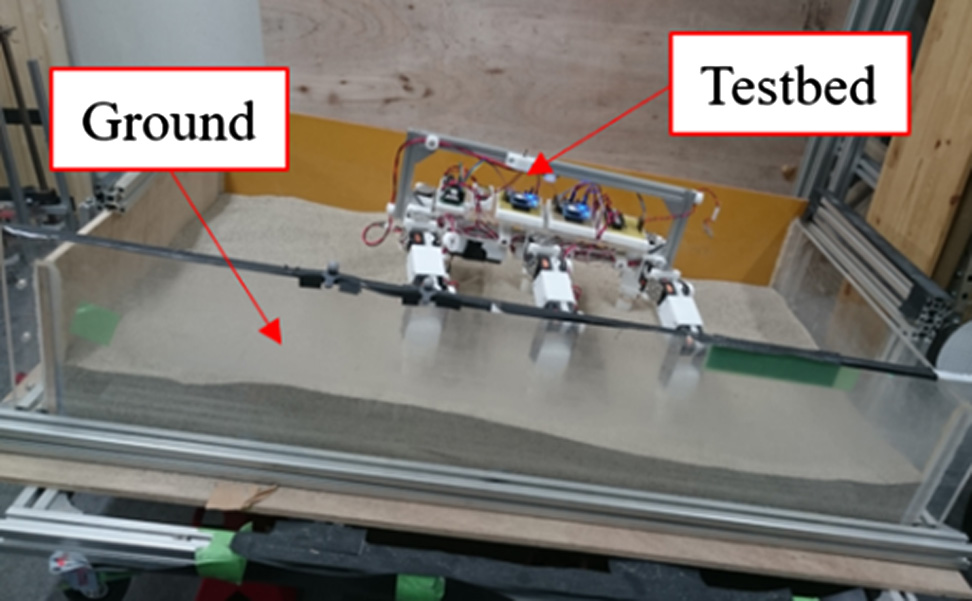 Fig. 16. Overview of slope walking experiment on the loose ground using testbed.
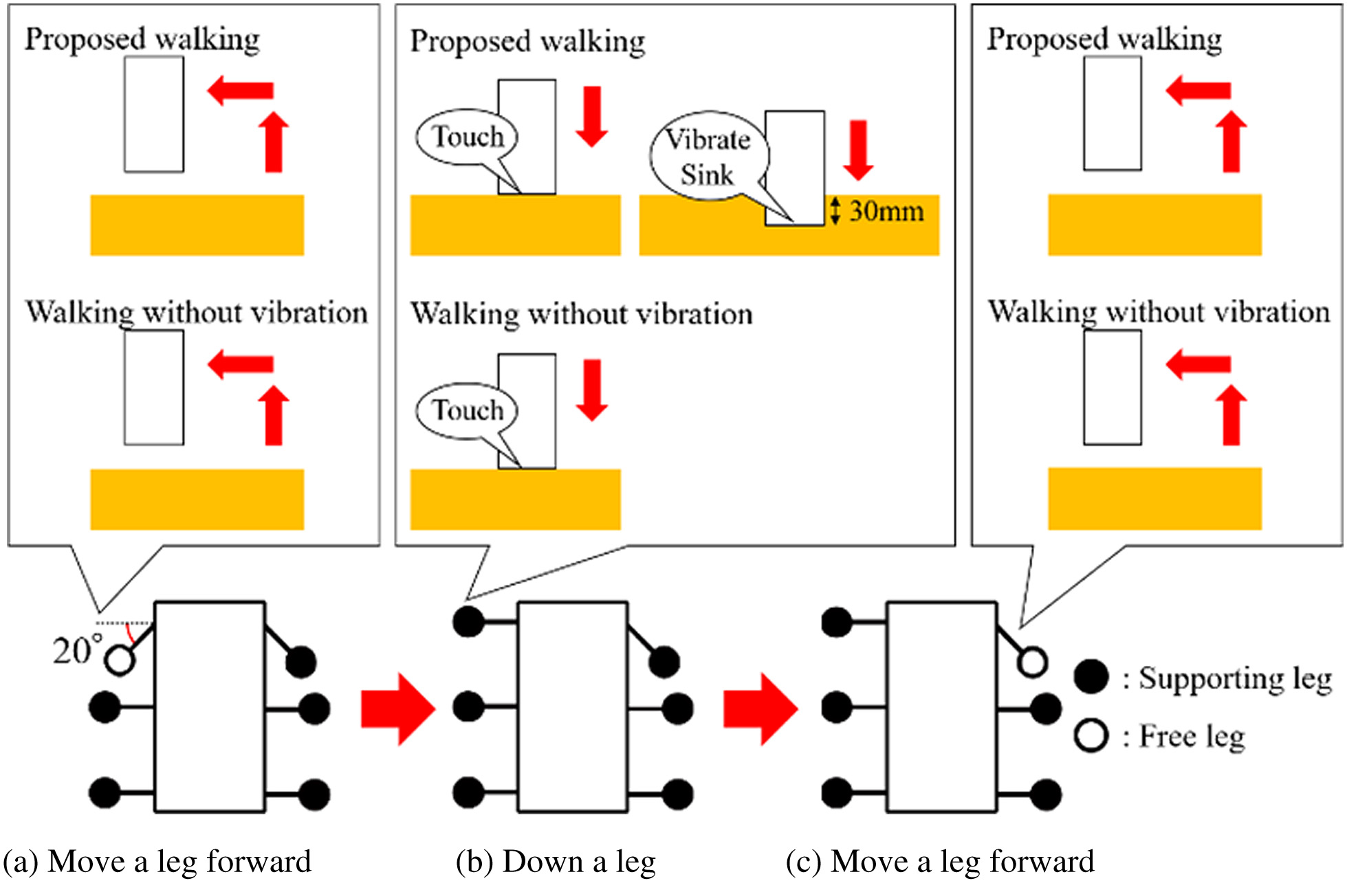 Fig. 17. Details of walking methods.
TABLE III. Specifications of Walking Methods
| Item | Value (value) |
|---|---|
| Stride | 47 mm |
| Time of 1 walking cycle | About 176 s (proposed walking) About 132 s (walking without vibration) |
| Walking speed | About 0.27 mm/s (proposed walking) About 0.36 mm/s (walking without vibration) |
| Vibration | Strong vibration |
TABLE IV. Condition for Slope Walking Experiment
| Item | Conditions (value) |
|---|---|
| Slope angle (°) | 0, 5, 10, 15, 20 |
| Number of trails | 5 |
| Walking steps | 5 steps |
| Motion capture system | OptiTrack Prime 13 |
| Kind of sand | Silica No. 5 |
Then, the testbed is explained. Table V shows the specifications of the testbed. The overview and the structure of the testbed are shown in Fig. 18. The leg of the testbed consists of three joints. The vibration motor is mounted in the leg. Judging the contact between the ground and the legs and measuring the posture of the testbed are conducted to evaluate the walking methods. The force sensor (FSR400) is used to judge the contact between the ground and the legs. These force sensors are attached to the toes, as shown in Fig. 19(a). The acceleration sensor (ADXL345) is used to measure the posture of the testbed. Fig. 19(b) shows the measuring direction about the posture of the testbed. The sampling frequency of these sensors is 2 Hz.
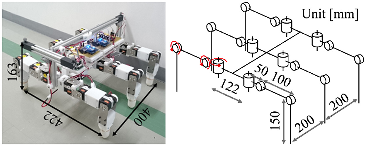 Fig. 18. Overview and structure of legged testbed.
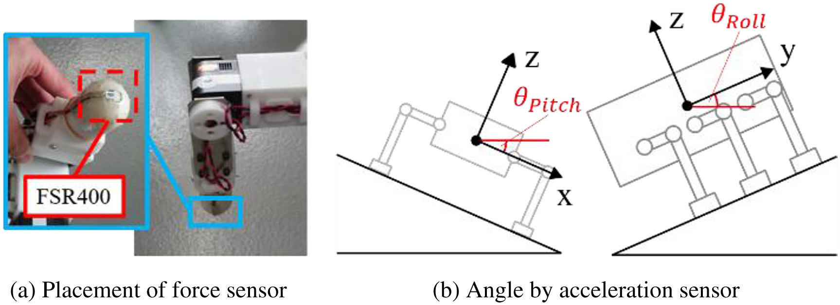 Fig. 19. Sensing system of legged testbed.
TABLE V. Specifications of Testbed
| Item | Conditions (value) |
|---|---|
| Weight (kg) | 5.9 |
| Size (mm) | H:163 W:422 L:400 |
| Servo motor | KRS6003R2HV ICS |
| Vibration motor | TP-2528C-24 |
| Force sensor | FSR400 |
| Acceleration sensor | ADXL345 |
| Sampling frequency | 2 Hz |
B.EVALUATION OF WALKING METHODS
In this experiment, Mos is calculated to evaluate the walking methods. In this section, calculation of Mos is explained. The term Mos is the moment around the touching point between the ground and the legs (Fig. 20). In this experiment, the force and the moment for the acceleration and the deceleration of the testbed are very small because the testbed walks static. Therefore, gravity is the primary force that the testbed is received. The term Mos is calculated from gravity that the testbed is received. The testbed consists of six legs and a body. The legs have three joints. Therefore, the testbed consists of 19 links. Each link is called Lij (Fig. 21). The term i is a leg’s number and j is a joint’s number. In each link, the mass, the size, and the coordinate of the center of gravity were already measured. The gravity of each link in the coordinate of testbed is calculated from (4)
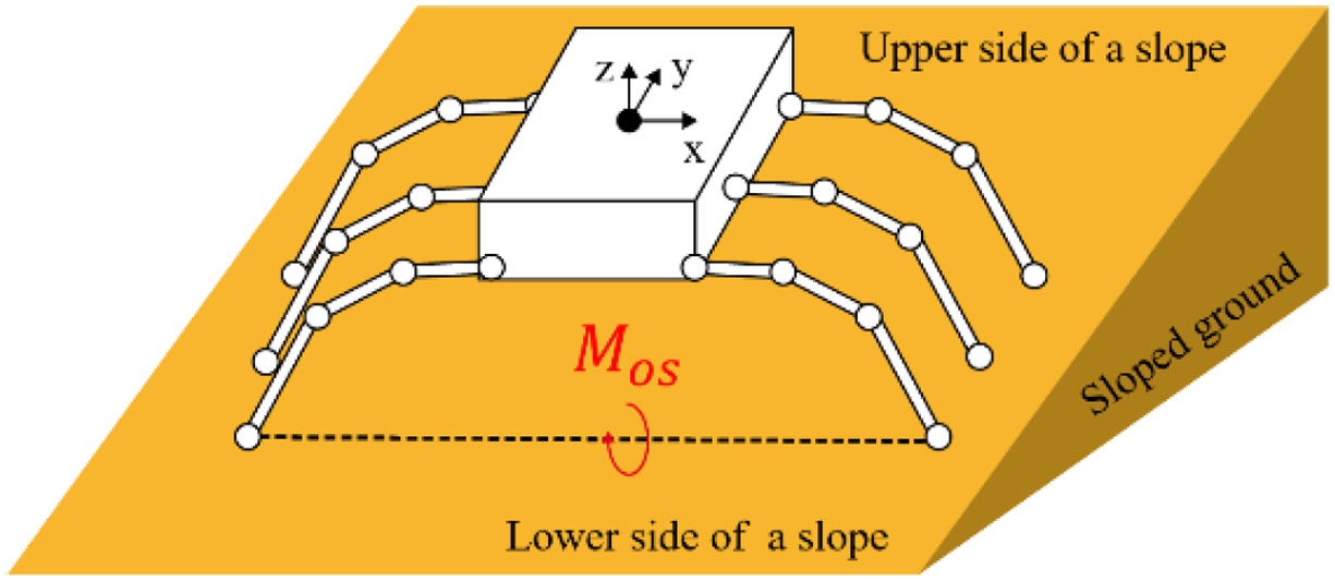 Fig. 20. Conceptual diagram of testbed on the slope.
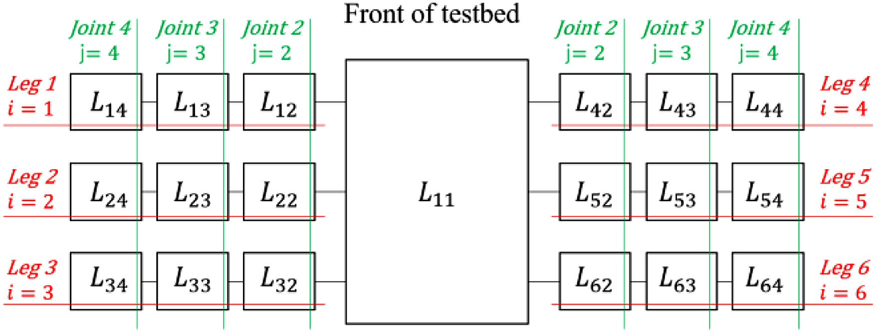 Fig. 21. Overview of links in the testbed.
where R is the rotation matrix of the x-, y-, and z-directions, θYaw, θPitch, and θRoll are the posture angle of the testbed on a slope, and the x-, y-, and z-directions are shown in Fig. 20. The term θYaw is approximately 0 because the testbed walks straight. The directions of θPitch and θRoll are shown in Fig. 19(b). The term mij is the mass of the link, which is ith of the leg and jth of the joint, and g is the gravitational acceleration. Then, the moment around the touching point between the ground and the leg is calculated. For example, Mk that is the moment around the touching point between the ground and the leg of kth is calculated from (5)
where pk is the position vector from the coordinate origin of the testbed to the point touching the ground and the leg of kth and pgij is the position vector from the coordinate origin of the testbed to the center of gravity of the link. These position vectors are calculated from (6) and (7). For example, Fig. 22 shows these position vectors in leg 1 (i = 1)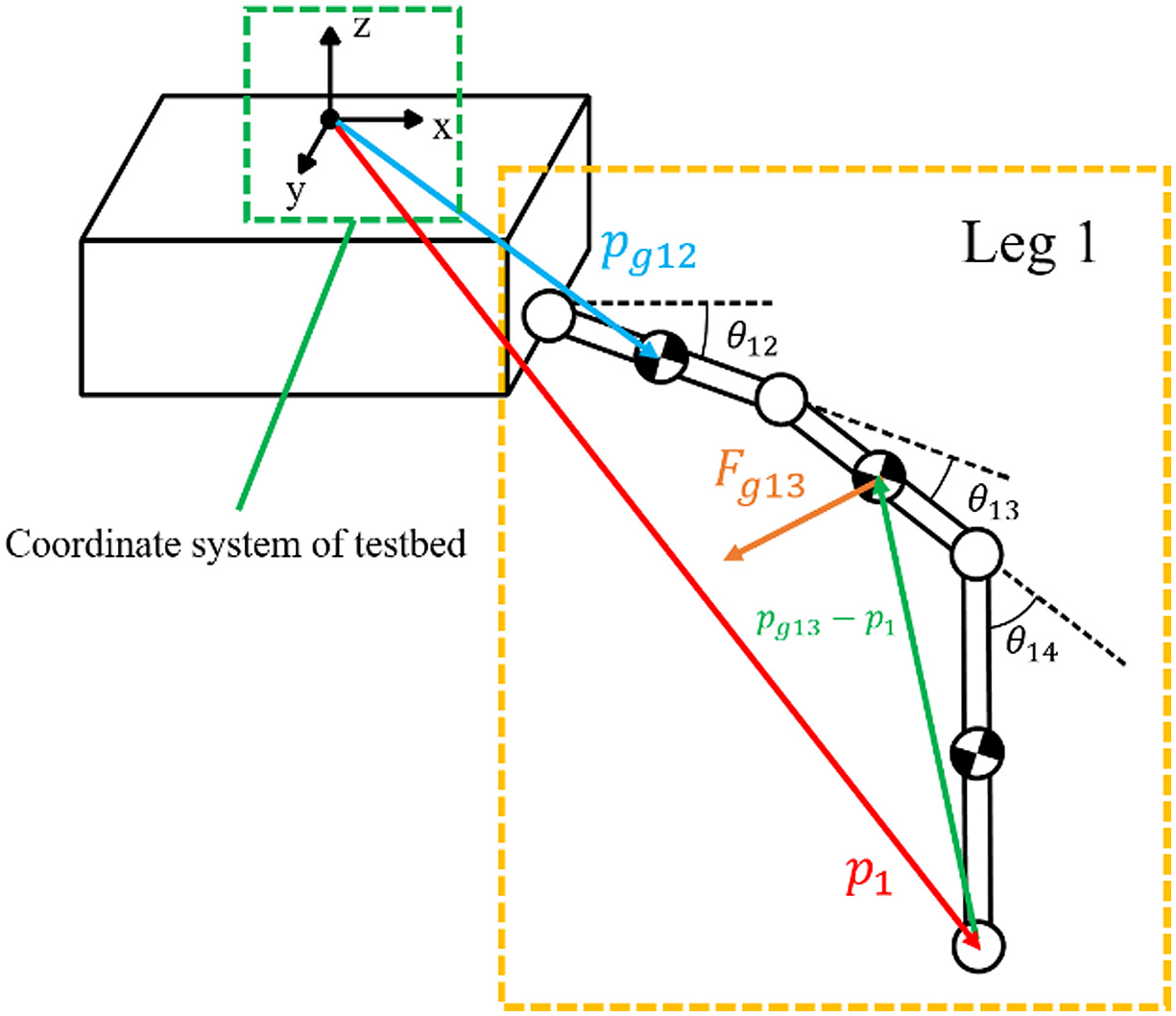 Fig. 22. Overview of position vectors in testbed.
where R is the rotation matrix and expressed in (8), θij is the angle of the link, which is ith of the leg and jth of the joint (Fig. 22), and θij consists of the angles in yaw, pitch, and roll directions
where plij is the position vector from the coordinate origin of the link to the joint between Lij and Lij+1 (Fig. 23(a)). The coordinate origin of the link is the same as the joint of the next link (Fig. 23(a)). The term plgij is the position vector from the coordinate origin of the link to the center of gravity of the link (Fig. 23(b)). The moment Mkn around the line segment connecting point k and point n is calculated from (9)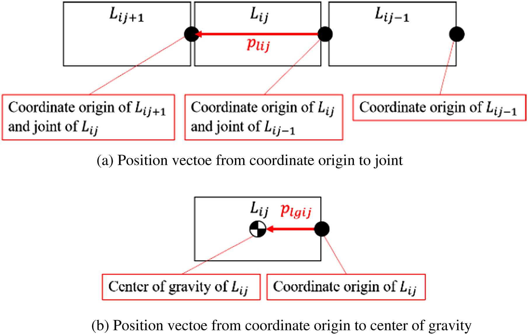 Fig. 23. Overview of position vectors in the link.
Their points are that the leg is touched the ground. The terms k and n are leg’s numbers. Calculation of Mos is divided into three cases because points touching the ground and the legs are changed in walking. The cases of calculating Mos are shown in (10) and Fig. 24
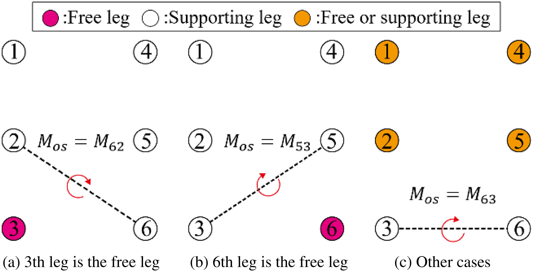 Fig. 24. Calculation cases of Mos.
When the 3rd leg is the free leg, Mos is M62. When the 6th leg is the free leg, Mos is M53. In other cases, Mos is M63. The larger the value of Mos is, the more difficult the testbed is to fall down. Table VI shows the symbols used for calculating Mos.
Moreover, the posture of the body in roll direction and the amount of movement by walking are measured to confirm the effectiveness of the proposed method. The amount of movement is measured by the motion capture system.
TABLE VI. List of Symbols That Used Calculating Moment on a Slope
| Description | Symbol |
|---|---|
| Leg number | i |
| Joint number | j |
| Gravity of link | Fgij |
| Posture of testbed in yaw direction | θYaw |
| Posture of testbed in pitch direction | θPitch |
| Posture of testbed in roll direction | θRoll |
| Mass of link | mij |
| Gravitational acceleration | g |
| Leg number that a leg touches ground | n and k |
| Moment around point that a leg touches ground | Mk |
| Position vector from coordinate origin to point that a leg touches ground (coordinate of testbed) | pi |
| Position vector from coordinate origin to center of gravity (coordinate of testbed) | pgij |
| Angle of joint | θij |
| Position vector from coordinate origin to joint (coordinate of link) | plij |
| Position vector from coordinate origin to center of gravity (coordinate of link) | plgij |
| Moment around the line segment connecting two points that a leg touches ground (coordinate of testbed) | Mkn |
| Moment on a slope | Mos |
C.RESULTS AND DISCUSSION OF A SLOPE WALKING EXPERIMENT
Table VI shows the result of the slope walking experiment. In Table VII, success means that the testbed could walk without falling down in all trials. Fall means that the testbed fell down in all trials. The testbed fell down on the loose ground with a lean of 15° and 20° when it used the walking without vibration. The testbed could walk using the proposed walking on all slopes without falling down. In this result, the proposed walking prevented a fall of the testbed. Moreover, the angle of a slope that the testbed can walk became large by using the proposed walking.
TABLE 7. Result of Slope Walking Experiment
| Slope angle | Proposed walking | Walking without vibration |
|---|---|---|
| 0° | Success | Success |
| 5° | Success | Success |
| 10° | Success | Success |
| 15° | Success | Fall |
| 20° | Success | Fall |
From Figs. 25 to 29, there are the graphs of time vs Mos in walking. In these graphs, the data of one trial are chosen because Mos, which was obtained in the same experimental conditions, was hardly different in all trials. Fig. 30 shows the change of Mos in one cycle of the walking. The term Mos was decreased at the beginning of this graph because the testbed raised the rear legs (Fig. 30). The term Mos was increased in the ending of this graph because the body of the testbed moved forward. From Figs. 25 to 27, time is expressed in percentage because the walking times are different in each walking method. These values of Mos were not different on a slope with 0° (Fig. 25). In Figs. 26 and 27, Mos in the proposed walking was larger than one in the walking without vibration on a slope with 5° and 10°. In this result, the testbed was difficult to fall down when it used the proposed walking. In Figs. 28 and 29, only Mos in the proposed walking is shown because the testbed fell down using the walking without vibration. In Figs. 28 and 29, Mos in the proposed walking is not decreased in each walking cycle. In these graphs, the larger the slope angle was, the smaller the Mos was. However, the testbed could walk using the proposed walking on all slopes without falling down. The reason for this result is considered that the resistance forces that prevent a fall of the testbed are caused. The friction force between the leg and the ground and the earth pressure is caused by sinking the legs in the ground (Fig. 31). Therefore, it is considered that the actual Mos is larger than the calculated Mos. In this result, falling down of the testbed was seemingly prevented by not only the effect of gravity but also other effects.
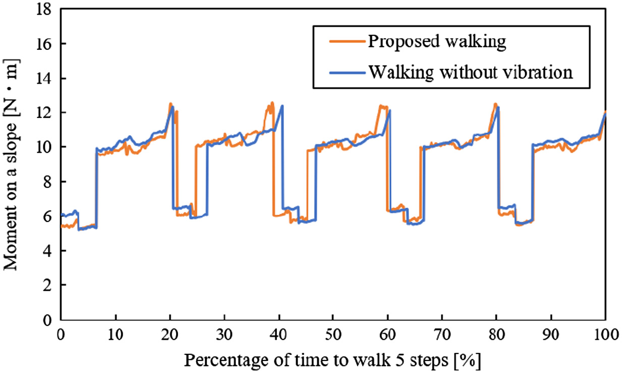 Fig. 25. Moment vs time on a slope with 0°.
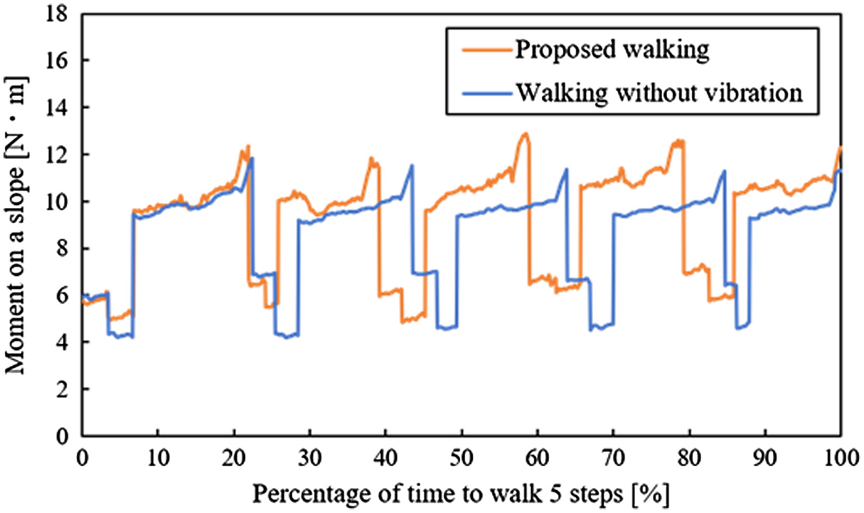 Fig. 26. Moment vs time on a slope with 5°.
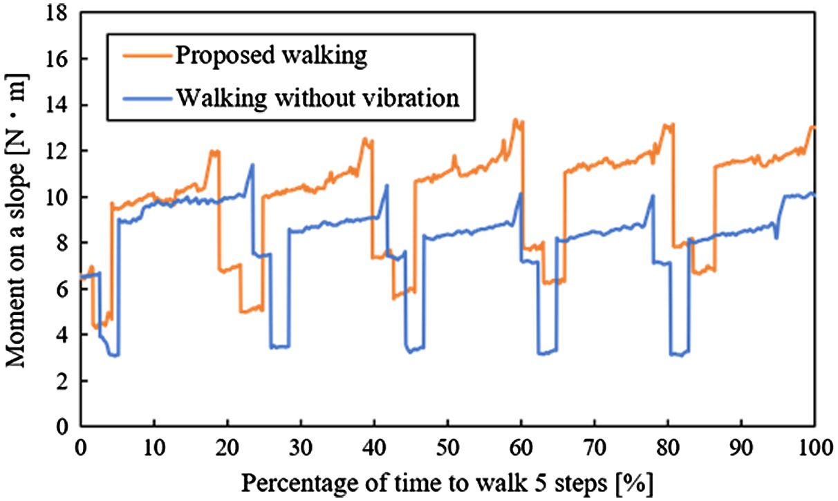 Fig. 27. Moment vs time on a slope with 10°.
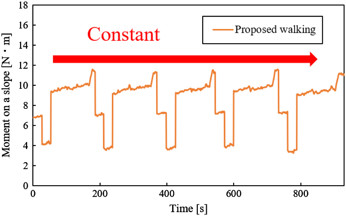 Fig. 28. Moment vs time on a slope with 15°.
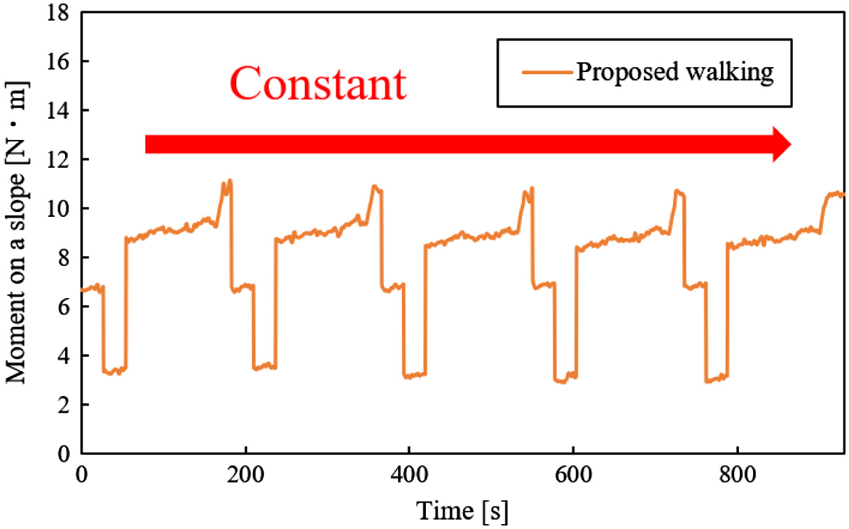 Fig. 29. Moment vs time on a slope with 20°.
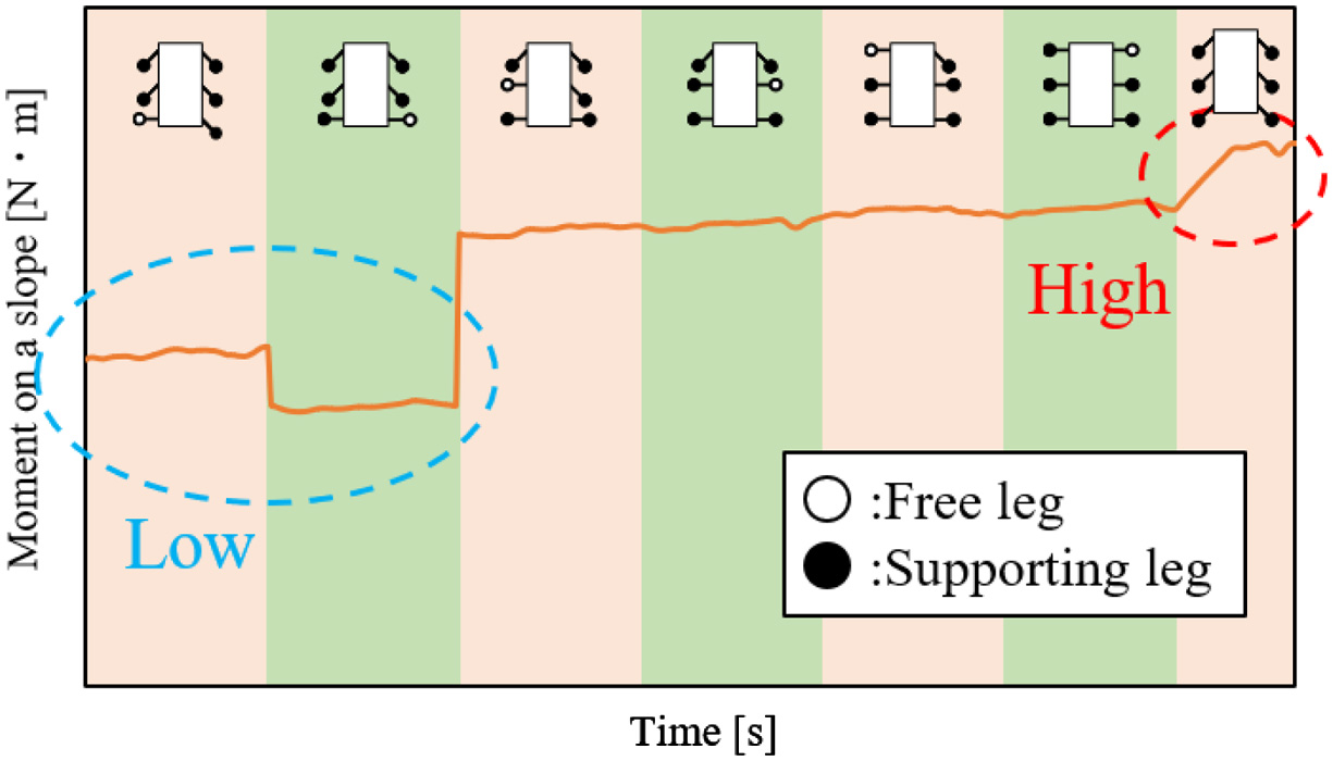 Fig. 30. Change of Mos in 1 walking cycle.
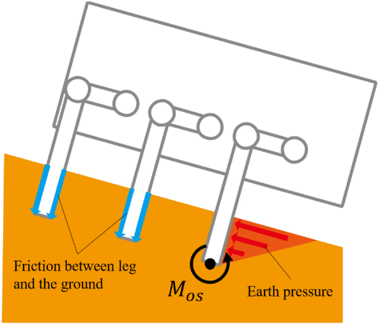 Fig. 31. Overview of resistance forces by subsidence.
From Figs. 32 to 36, there are the graphs of time vs testbed’s posture. In these graphs, the data of one trial are chosen because the posture of the testbed, which was obtained in the same experimental conditions, was hardly different in all trials. In these graphs, the posture of the testbed is the angle in roll direction (Fig. 19(b)). Their values of the testbed’s postures were not different on a slope with 0° (Fig. 32). In Figs. 33 and 34, the posture of the testbed in the proposed walking was smaller than one in the walking without vibration on slopes with 5° and 10°. In Fig. 35, the posture of the testbed in the proposed walking was not increased. However, the posture of the testbed in the proposed walking was increased in Fig. 36. Therefore, the proposed walking method has the feature that the posture angle of the testbed is decreased. However, the larger the angle of a slope is, the less effective this feature is.
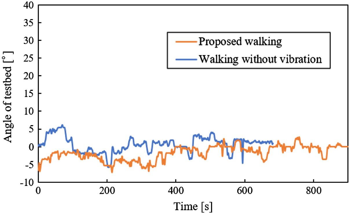 Fig. 32. Posture of testbed vs time on a slope with 0°.
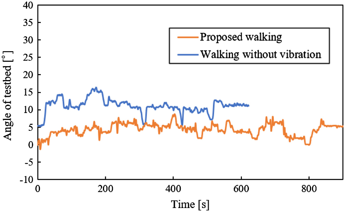 Fig. 33. Posture of testbed vs time on a slope with 5°.
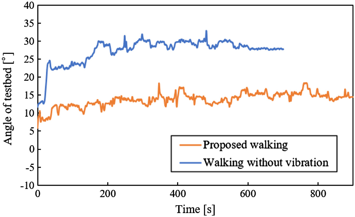 Fig. 34. Posture of testbed vs time on a slope with 10°.
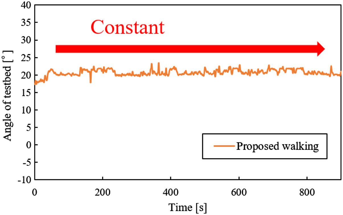 Fig. 35. Posture of testbed vs time on a slope with 15°.
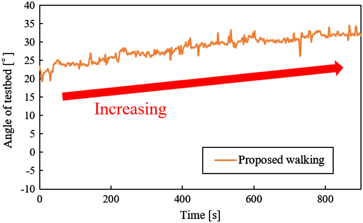 Fig. 36. Posture of testbed vs time on a slope with 20°.
Fig. 37 shows the graph comparing the amounts of movement. The amount of movement in the proposed walking is larger than one in the walking without vibration. The testbed slipped and did not move forward in a slope of 10° when it walked using the walking without vibration. In this result, the running performance was improved by using the proposed walking.
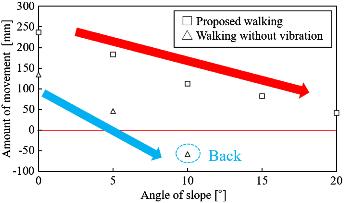 Fig. 37. Amount of movement in each walking.
Finally, we discuss the advantage and weaknesses of the proposed walking. On the advantage, a legged rover is difficult to fall down because the posture angle of a legged rover is decreased by using the proposed walking. Moreover, the amount that a legged rover walks becomes large by using the proposed walking. On the weakness, the time during one cycle of walking motion in the proposed walking is longer than one in the walking without vibration. The reason is that the time of vibrating legs is added in the proposed walking. In this study, shortening of vibrating time is not addressed yet. This weakness will be solved when the relationship between vibrating time and running performance is confirmed in the future study.
V.CONCLUSION
In this study, a walking method that prevented a fall of the legged rover was proposed. In the proposed walking method, the leg was sunk by giving vibration to the ground. The posture of the rover was changed to prevent a fall of the rover by sinking the leg. First, the relationship between the kind of vibration and the subsidence of the leg was confirmed. In this experiment, the rod was penetrated into the loose ground. Moreover, the resistance force that the rod was received from the ground was measured. The experimental results are shown below:
- •The rod is easy to sink to the ground by giving vibration.
- •The larger the vibratory force is, the smaller the resistance force is.
In these results, it was possible that the rover inclines forward by giving vibration to the ground. Finally, the legged testbed walked on the loose ground with a slope using the proposed walking method. The experimental results are shown below:
- •The testbed is difficult to fall down when it used the proposed walking.
- •The angle of a slope that the testbed can walk becomes large by using the proposed walking.
- •The posture angle of the testbed is decreased by using the proposed walking.
- •The amount of movement in the proposed walking is larger than one in the walking without vibration.
In these experimental results, it was confirmed that the proposed walking method was effective.
The value of Mos was decreased in high angle slopes but the testbed could walk without falling down. The reason for this result is considered that the resistance forces that prevent a fall of the testbed are caused. In the future study, Mos that includes these resistances will be calculated. The proposed walking will be able to be evaluated accurately by including these resistances. Moreover, the time during one cycle of walking motion in the proposed walking was longer than one in the walking without vibration. Running speed can be increased by shortening the time during one cycle of walking motion. Therefore, the time during one cycle of walking motion should be short. In future study, the relationship between vibrating time and running performance will be confirmed to short vibrating time.