I.INTRODUCTION
One of the promising propulsion devices for mobile robots designed to perform various technological operations on an unorganized surface is a walking propulsion device. Such propulsion device is currently object of research [1]–[5]. Various mathematical models have been considered that describe the dynamics of controlled movement of both multilegged and bipedal robots [6]–[11]. For such robots, one of the important tasks is to determine the optimal models of movement [12,13].
It is obvious that mobile robots with walking propulsion devices are capable of overcoming obstacles without any physical contact with them and have a prerequisite to obtain perfect maneuverability. The perfect maneuverability means that the body of robot can make any predefined plane motion [14]. This is the main advantage of walking mobile robots in comparison with traditional types of drives (wheels, trucks, etc.). The disadvantages are low speed and energy efficiency. This is caused by the properties of the walking machines as an unbalanced mechanism to interact discretely with supporting ground in the process of transfer and ensure the movement of the foot along an arbitrary path [15].
In case of moving on unknown terrain, there is still the need to ensure the movement of mobile robot without gliding or stumbling. The law of control to obtain this comfortability is known [16]. The knowledge of geometrical characteristics of ground (the height of obstacles, distances between them and to them, etc.) can affect both law of control for leg transfer and its trajectory. For example, it can copy the ground profile.
The trajectory depends on the optimality criterion. The latter can consist of several indexes, for example, minimum heat loss in drive motors, minimum root mean square (RMS) power developed by engines, and minimum distance traveled [17,18]. These indexes can be compiled in complex optimality criterion to determine the boundaries of the Pareto-optimal motion modes [19].
For walking robots with orthogonal-rotary propulsion devices, for example, for the machine “Ortonog” (Fig. 1), the laws of vertical and horizontal movements of the propeller foot are established in accordance with the optimality criterion consisting of several indicators [20, 21].
 Fig. 1. Walking machine “Ortonog.”
However, the task of determining the optimal programmed foot movement of the propulsion devices of an underwater mobile robot both in the horizontal and vertical directions simultaneously while overcoming obstacles was not considered. This task is especially relevant for underwater robots because movement is characterized by much greater forces of resistance to the movement of the feet in a dense environment compared with the air environment and the unevenness of the bottom, which makes it necessary to step over fairly large obstacles.
It is important to note that different environment can affect not only priority of indexes but also the design of mobile robot itself. For purposes of this paper, it is accepted that the characteristics of mobile robot meet requirements of environment.
II.STATEMENT OF THE PROBLEM
The foot of underwater walking mobile robot is viewed as material point. The movement of the point in the vertical plane is analyzed. In this case, the material point means the center of the foot of a walking robot, the optimal trajectory of which is determined in this paper. One transfer is characterized by following features: starting point A, the length of step L, the height of obstacle H, the distance to the obstacle S, destination point B, and the height of destination point h (Fig. 2). Forces considered are weight P, forces of resistance to movement Rx, Ry, proportional to speeds of movement , , and forces developed by drives of vertical Т and horizontal F displacement.
 Fig. 2. Design scheme for foot transfer.
The movement is described by the system of differential equations:
where μx and μy are the coefficients of viscous resistance of a liquid, depending on the shape and geometrical dimensions of the foot mass m.Boundary conditions are set at
The dimensionless indexes of quality of the movement Ij are introduced. The sum of these indexes form complex optimality criterion I:
where kj is the weight coefficients, defined up to a constant factor and selected in accordance with the significance of each indexwhere I1 is the index of quality of the movement, characterizing heat loss in drive motors, α1 and α2 are known constants characterizing drive motors, and А is an arbitrary reference work defined, for example, А = mgHwhere I2 and I3 are the indexes of quality of the movement, characterizing the square of RMS acceleration, and g is the acceleration of gravitywhere I4 is the index of quality of movement, characterizing the square of RMS of power of the drives.The task is to find the laws of movement x = x(t) and y = y(t) to ensure the overcoming of obstacle by foot of walking machine, to satisfy the boundary conditions (2) and delivers minimum to at least one of the indexes (4)–(6).
III.THE METHOD OF PROBLEM SOLVING
The method of solving the problem is based on splitting the movement into two stages: before and after overcoming the obstacle.
First stage: 0 < t < τ1:
Second stage: 0 < t < τ – τ1:
Each stage is characterized by control parameters τ1, U. For each stage, the problem of minimum of functional (3) must be solved with the help of Euler–Poisson equations [22]:
whereIf k4 = 0, then (9) becomes
whereEquation (10) is solved at each stage with regard to boundary conditions (7) and (8).
The optimality of foot transfer according to selected criterion (3) at each stage together with the choice of control parameters τ1, U provide the optimality of entire movement mode [17].
The solutions of differential equations (10) at each stage are as follows:
Constants Ci, Bi (i = 1 … 4) are determined from the boundary conditions.
As a result, all indexes of quality of movement and complex optimality criterion are determined in accordance with the differential equation of transfer movement (1) and expression (11)
However, the most important characteristic when choosing a drive is the maximum drive power required to ensure the rapid movement of the propulsion device from one position to another. If there is a need to minimize the RMS power while horizontal movement of the foot of the propulsion device, then the criterion (12) can be represented in the form:
IV.THE MODEL TASK OF DETERMINING THE OPTIMAL MODE OF MOVEMENT AND ANALYSIS OF RESULTS
To solve the problem, it is initially required to determine the control parameters τ1, U that provide minimum for complex criterion (12), or one of indexes of quality Ij, for example, index of heat loss I1.
For model task, let us consider the walking mobile robot “Ortonog” with dual walking mechanism. The body of robot is moving uniformly rectilinearly at a constant speed V. The characteristics of mechanism are the mass m = 70 kg, the stride length L = 0.91 m, and constants characterizing drive motors α1 = α2. The speed V is related to the stride length and the foot transfer time τ as
The basic ground profile and robot position are characterized by the following parameters: Н = 0.3 m, S = 0.3L = 0.273 m, and h = 0.
Thus, the variable parameters are the constructive λx, λy, which characterize the streamlining of the propulsion device by the external environment – water, the speed of the robot V, the desired control actions U = γV, τ1 = ɛτ = ɛ(L/2τ), which are convenient to specify dimensionless parameters γ and ɛ, and the geometric characteristics of the soil profile H, S, h, varying depending on specific conditions.
The mathematical model shows the dependence of indexes of quality (4) and (5) included in complex criterion (3) from control parameters.
In Fig. 3, the dependence of index of heat loss in drive motors I1 on dimensionless control parameters ɛ = τ1/τ and γ = U/V is shown for known geometric characteristics of the ground profile and various values of the vehicle speed. The graphs show that there is an optimal mode of foot transfer over an obstacle, characterized by the parameters of the machine. Their analysis shows that at low and high values of the speeds of movement of a mobile robot, the index of heat loss I1 reaches high values, whereas at a certain value of V, the index I1 reaches a minimum.
 Fig. 3. The dependence of index of heat loss in drive motors I1 on dimensionless control parameters ɛ and γ: (1) V = 0.4 m/s, (2) V = 0.7 m/s, and (3) V = 1 m/s.
Dependences of the index of heat loss in drive motors I1 (Fig. 4) and the dimensionless square of the RMS horizontal acceleration I2 (Fig. 5) on the dimensionless ɛ = τ1/τ and γ = U/V for various geometric parameters of the ground profile, characterized by the location of the obstacle S. Their analysis shows that there is an optimal mode of foot transfer over an obstacle.
 Fig. 4. The dependence of index of heat loss in drive motors I1 on dimensionless control parameters ɛ and γ: (1) S = 0.1L, (2) S = 0.3L, (3) S = 0.5L, and (4) S = 0.7L.
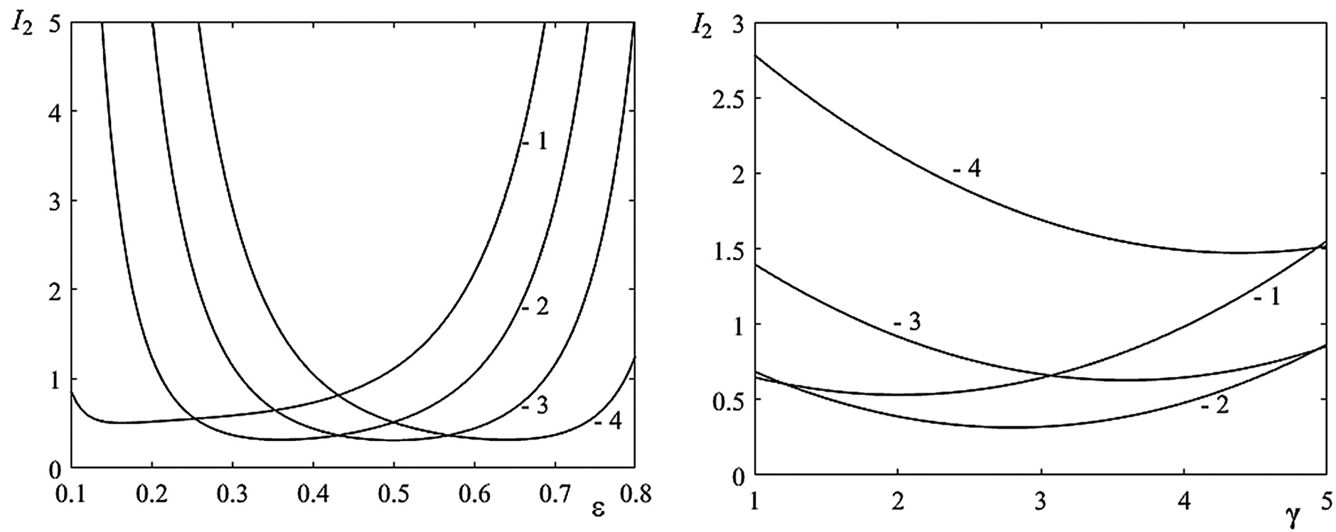 Fig. 5. The dependence of the index of the dimensionless square of the RMS horizontal acceleration I2 on the dimensionless ɛ and γ: (1) S = 0.1L, (2) S = 0.3L, (3) S = 0.5L, and (4) S = 0.7L.
The optimal modes of movement shown in Figs. 3–5 consider only one of the possible indexes. If we consider the significance of each of the indexes by weight coefficients kj, then the particular indexes change (Figs. 6 and 7) and are controversial. With the growing importance of one of them, the other index decreases. The analysis of such dependencies allows us to determine the Pareto optimal boundaries, which is decision support for the robot control system.
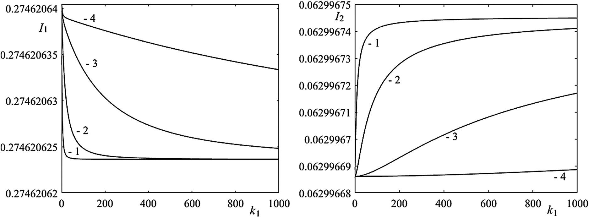 Fig. 6. Dependences of the index of heat loss in drive motors I1 and the dimensionless square of the RMS horizontal acceleration I2 on weight coefficients k1: (1) k2 = 1, (2) k2 = 10, (3) k2 = 100, and (4) k2 = 1000.
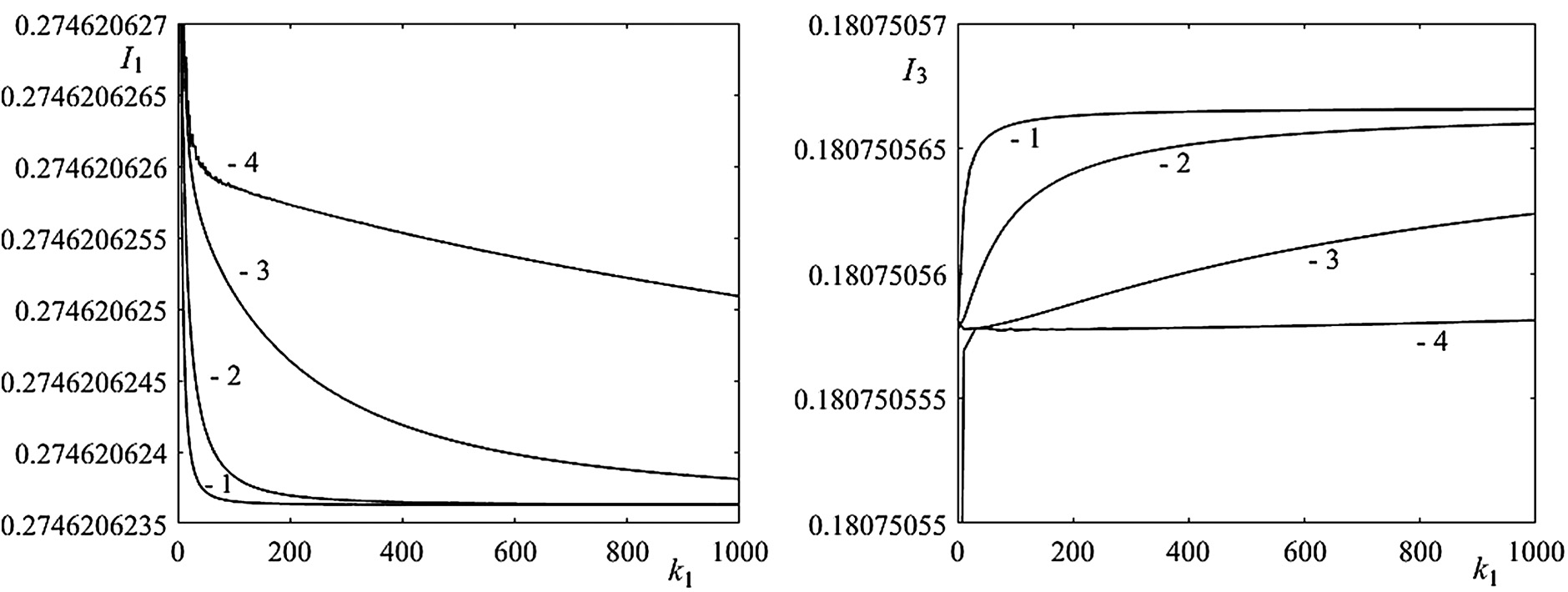 Fig. 7. Dependences of the index of heat loss in drive motors I1 and the dimensionless square of the RMS vertical acceleration I3 on weight coefficients k1: (1) k2 = 1, (2) k2 = 10, (3) k2 = 100, and (4) k2 = 1000.
If only the power of the drives is taken into account as a criterion, and in the particular case, only the power of the horizontal movement of the foot, then instead of (10), there is an equation:
Boundary conditions are set:
- (1)at the beginning of the step of transferring the foot of the propulsion at
- (2)upon reaching an obstacle at a distance S from the initial position of the foot during the time τ
The solution of (15) has the form:
where .Taking into account (16), C2 = −C1 = C.
Then,
and the constant C is determined from (17)
The dependences of speed V at the moment τ of overcoming the obstacle from the time τ are shown in Fig. 8. Fig. 9 shows the dependence of criteria (13) of minimum of RMS power from the time τ.
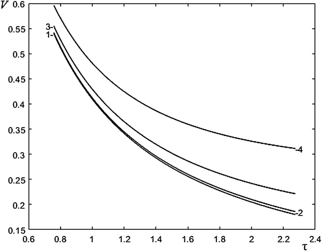 Fig. 8. The dependences of speed V at the moment τ of overcoming the obstacle from the time τ: (1) μx = 10 kg/s, (2) μx = 30 kg/s, (3) μx = 50 kg/s, and (4) μx = 70 kg/s.
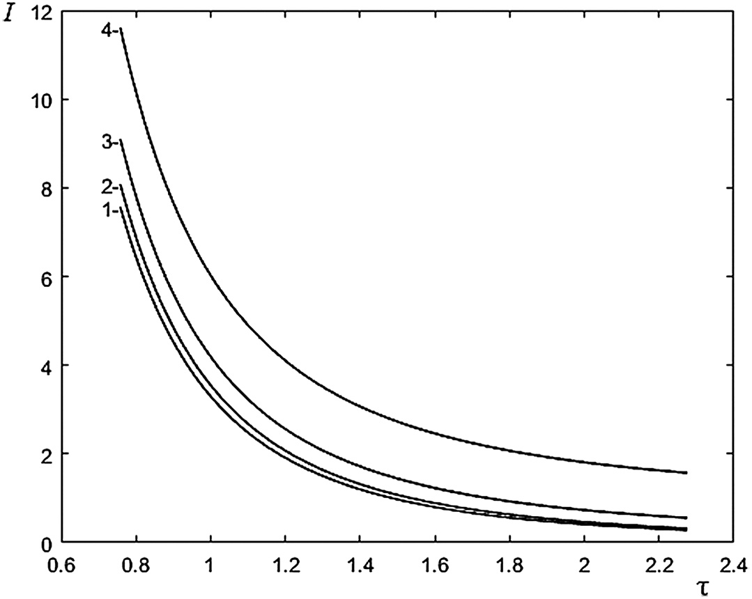 Fig. 9. The dependence of criteria (13) of minimum of RMS power from the time τ: (1) μx = 10 kg/s, (2) μx = 30 kg/s, (3) μx = 50 kg/s, and (4) μx = 70 kg/s.
V.CONCLUSIONS
A design scheme was proposed, and a mathematical model was developed to describe the dynamics of the movement of the transferred foot of the walking propulsion device of an underwater mobile robot.
Indexes of quality of movement were formulated, which determined the optimal control modes for the transfer of the foot of a walking propulsion device when overcoming obstacles, and methods for their determination were developed.
The dependences of indexes of quality on the speed of the robot, the control parameters ɛ, γ, and the geometric parameters of the ground profile S, H were determined.
A method for constructing the Pareto-optimal boundaries of variable parameters was developed.
The proposed solution of the problem possessed a significant advantage along with the already known approaches for solving such problems through the use of a developed information-measuring system and the combination of the simultaneous movement of orthogonal devices in the horizontal and vertical directions.
The calculated data and dependencies are planned to be confirmed experimentally.