I.INTRODUCTION
With the development of the electronics industry and its close integration with the automotive industry, automotive electronic control technology has gradually been widely used in automobiles [1]. In this context, the electric window lift controller came into being. The operating comfort and safety of the electric window lifter brought unprecedented convenience to the passengers, which was widely recognized by the industry. Although the power windows have improved the comfort and control convenience of the car, the introduction of automatic functions in the power windows has made the windows in the process of automatically rising, and the safety accidents of the occupants of the power windows have also occurred constantly, threatening the personal safety of passengers, especially accidents where children are injured or even killed frequently occur [2]. Therefore, it is an inevitable trend to design a power window with anti-pinch function without affecting the comfort and ease of operation of the vehicle, which is of great significance [3].
From a safety perspective, some developed countries such as Europe and the United States have formulated corresponding laws and regulations, which clearly stipulate the performance requirements of the window anti-pinch system [4]. For example, the 74/60/EEC regulations in Europe and the FMVSS118 regulations in the United States clearly stipulate that anti-pinch power windows are the standard configuration of automobiles [5]: passenger cars must have smart anti-pinch functions [6]. China has also promulgated the national standard GB11552-2009 [7] for internal protrusions in passenger cars. The specification states that when the opening of power window is from 4 to 200 mm, the device should retract the window before the clamping force is greater than 100 N [8].
In China, BAIC Motor Group Co., Ltd., proposed an anti-pinch algorithm based on dual Hall sensors in 2019 [9]: by real-time detection of the speed change and movement direction of the window motor, combined with the changes of power supply voltage and external temperature, mechanical structure and adhesive strip aging and other factors, and then using compensation and adaptive methods, the problem of the current anti-pinch algorithm of the window is solved [10]. In foreign countries, American ATMEL semiconductor company proposed a window glass anti-pinch control algorithm based on motor current and motor speed change rate [11]. By comparing the difference between the current value and the reference value and the preset threshold value, combined with the positive and negative motor speed change rate, it can judge whether the anti-pinch function needs to be turned on.
In this paper, four windows can be intelligently controlled by a window regulator. The controller can intelligently detect and update the motor current in real time, use the changed current to detect anti-pinch, and use the ac component (ripple) contained in the current to calculate the operating position of the window.
Contributions: First, proposed an intelligent anti-pinch method based on motor current detection. Second, an intelligent speed regulation method for power windows is proposed.
Section I of this paper introduces the background and contribution of this paper, section II explains the system structure design of power windows, section III explains the intelligent anti-pinch design, and the section IV analyzes the intelligent calculation method of the window glass position. Section V explains the intelligent speed regulation method, section VI analyzes the test results, and Section VII is a summary.
II.SYSTEM STRUCTURE DESIGN
The S12G128 chip produced by NXP is used as the main control chip of the system. It needs to collect the lift switch signals of the four windows in real time and receive CAN messages sent by BCM. Then, the main control chip processes the corresponding control strategy for the input switch signal, and outputs the processed signal to the corresponding door to realize the control of the corresponding window. The hardware design framework of DCU system is shown in Fig 1.
 Fig. 1. System hardware design framework.
Electric window regulator collects the voltages on both ends of the sampling resistor by motor current sampling circuit, and simple calculation to obtain real-time current when the motor running, and then input to the MCU [12]. The current input to the MCU is divided into two parts. The first part is used for anti-pinch detection and locked-rotor detection to realize intelligent anti-pinch and locked-rotor functions. The second part is processed by the corresponding software algorithm to calculate the real-time window glass position, provide an anti-pinch area for the anti-pinch function.
III.SMART ANTI-PINCH DESIGN
A.ANTI-PINCH DESIGN PRINCIPLE
The realization of anti-pinch of electric Windows needs to consider two core problems: the accurate judgment of the position of the window and the judgment of the anti-pinch force. The judgment of anti-clamping force is based on the physical characteristics of the motor, so the physical model of the window motor is first established [13], as shown in Figs. 2 and 3.
 Fig. 2. Mechanical characteristics of motor.
 Fig. 3. Electrical characteristics of motor.
The following physical expressions can be listed from Figs. 2 and 3:
Equation (5) is a frequency domain formula, it can be obtained by combining the Laplace transform of formula (1)–(4).
It can be seen from (5) that since the voltage at both ends of the armature U(t), the moment of inertia of the motor J, the armature self-inductance L, and the armature equivalent resistance R are fixed for a certain motor system. Therefore, when the resistance and friction coefficient f in the rotation of the motor increase, the motor current i(t) must increase accordingly, and the relationship is satisfied. That is to say, when the window encounters obstacles in the rising process, the resistance increases, so that the motor speed Ω(t) becomes smaller, and the current increases accordingly.
B.REALIZATION OF ANTI-PINCH FUNCTION
Because the anti-pinch function of the power window is only applicable to the process of the window glass rising, it is necessary to study the current characteristics of the motor rising process. Fig. 4 shows the current waveform when the window glass encounters an obstacle during the ascent of the window.
 Fig. 4. Current waveform when the window meets an obstacle.
As can be seen from Fig. 4, when the window meets obstacles, the current is directly proportional to the resistance of the window glass [14]. However, the slope of current change when the window encounters obstruction is much less than the slope of the motor when it is blocked. According to this characteristic, the area integral method can be adopted to detect the anti-pinch: Taking a period of time Ts on the motor current curve, and integrating the rectangular area enclosed by the horizontal axis (time) and the vertical axis (current). Within the determined time T = t1−t0, the area integral is,
If S > S0 (anti-pinch threshold) within time T. When anti-pinch is detected, the window regulator controls the window to automatically reverse [15].
C.ADAPTIVE AND SELF-LEARNING
The self-adaptive and self-learning functions are suitable for the false anti-pinch caused by wear and aging of the sealing strips, transmission mechanisms, motor, and other components. This function can ensure that the anti-pinch function of the power window can operate stably under different environmental conditions.
Self-adaptive: During the operation of the motor, there will be many burrs in the current. These burrs can be filtered out through self-learning and the available current can be saved. Self-learning: When the window glass finishes 20 complete strokes, it starts to re-learn the anti-pinch threshold: When the window glass passes through the anti-pinch area, the area integral S is obtained by the area integration method as the new anti-pinch threshold S0. The flow chart of adaptive and self-learning is shown in Fig. 5.

IV.INTELLIGENT CALCULATION OF WINDOW GLASS POSITION
A.PRINCIPLE OF RIPPLE GENERATION
Since the electric window regulator only allows the anti-pinch function to be executed when the window is rising and locating in the anti-pinch area[16]. Therefore, it is necessary to continuously detect the position of the window glass during the ascent of the window to determine whether it enters the anti-pinch area, and the position of the window glass can be calculated by the number of ripples.
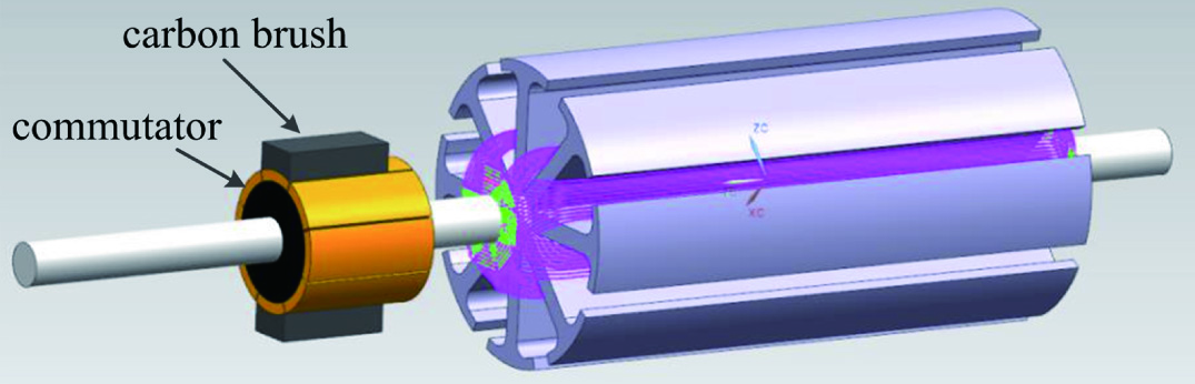
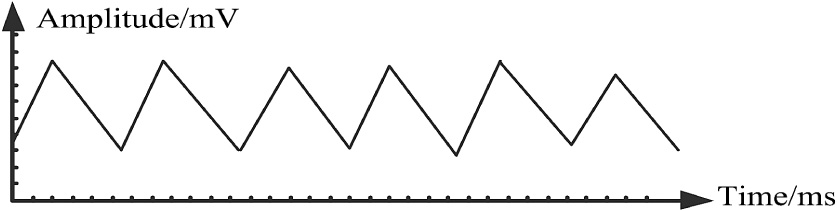
The principle of ripple generation: as shown in Fig. 6, the rotating shaft of dc brush motor is equipped with a commutator (N slot). A pair of carbon brushes rotate on the circumference of the commutator and transmit current [17]. During this process (The carbon brushes are in contact with the commutator segments at the same time during the commutation process), ripple current is generated due to the difference in instantaneous loop resistance. Therefore, the ripple of the same frequency is superimposed on the dc component of the current, so the current collected from the motor end during normal operation of the motor will show periodic changes [18], as shown in Fig. 7.
B.RIPPLE COUNT AND WINDOW GLASS POSITION CALCULATION
Using the phase difference method to count the ripple:
When the motor is running, compare the current collected currently (solid-blue line in Fig. 8) with the current(solid-red-dotted line in Fig. 8) collected for the previous Nth time(n depends on the specific situation). By comparing the results (the rear phase is greater than the front phase), the ripple count is achieved.
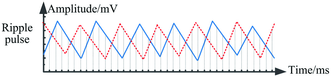 Fig. 8. Ripple to square wave.
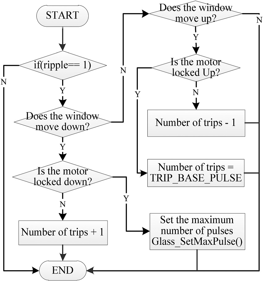
Since the motor rotates once a week, a fixed number of ripple will be generated, so there is a linear relationship between the travel distance of the window motion and the number of current ripple of the motor [19]. When the window moves upward, the number of window travel distance decreases by 1 for each ripple detected, when the window moves downward, the number of window travel distance increases by 1 for each ripple detected, the flow chart shown in Fig. 9.
V.INTELLIGENT SPEED REGULATION
When the window moves to the top/bottom hard dead center, the window glass will hit the top/bottom of the window at a fast speed, which makes the motor and its mechanical structure vulnerable to damage and shorten its service life [20].
In order to solve this problem, a method of intelligent speed regulation of the PWM motor is proposed: Before the window glass hits the hard dead center, by acquiring the glass position and adjusting the duty cycle of the MOS transistor, the motor speed is controlled to decelerate the window glass to the minimum duty cycle position or hard dead center. The flow chart is shown in Fig. 10.

VI.TEST RESULTS
A.SMART ANTI-PINCH
When the system voltage is 13.5 V and other conditions remain unchanged, the motor current can increase to 190 mV at the moment of starting the motor, and the motor starting time is about 80 ms.
During the normal rising process of the window glass, the current increases slowly due to the effect of the rubber strip. When the window glass runs to the anti-pinch area, under the influence of external resistance, the motor current increases significantly. When it reaches a certain threshold (if after the anti-pinch force is 80 N), The system will automatically reverse to stop. As shown in Fig. 11.
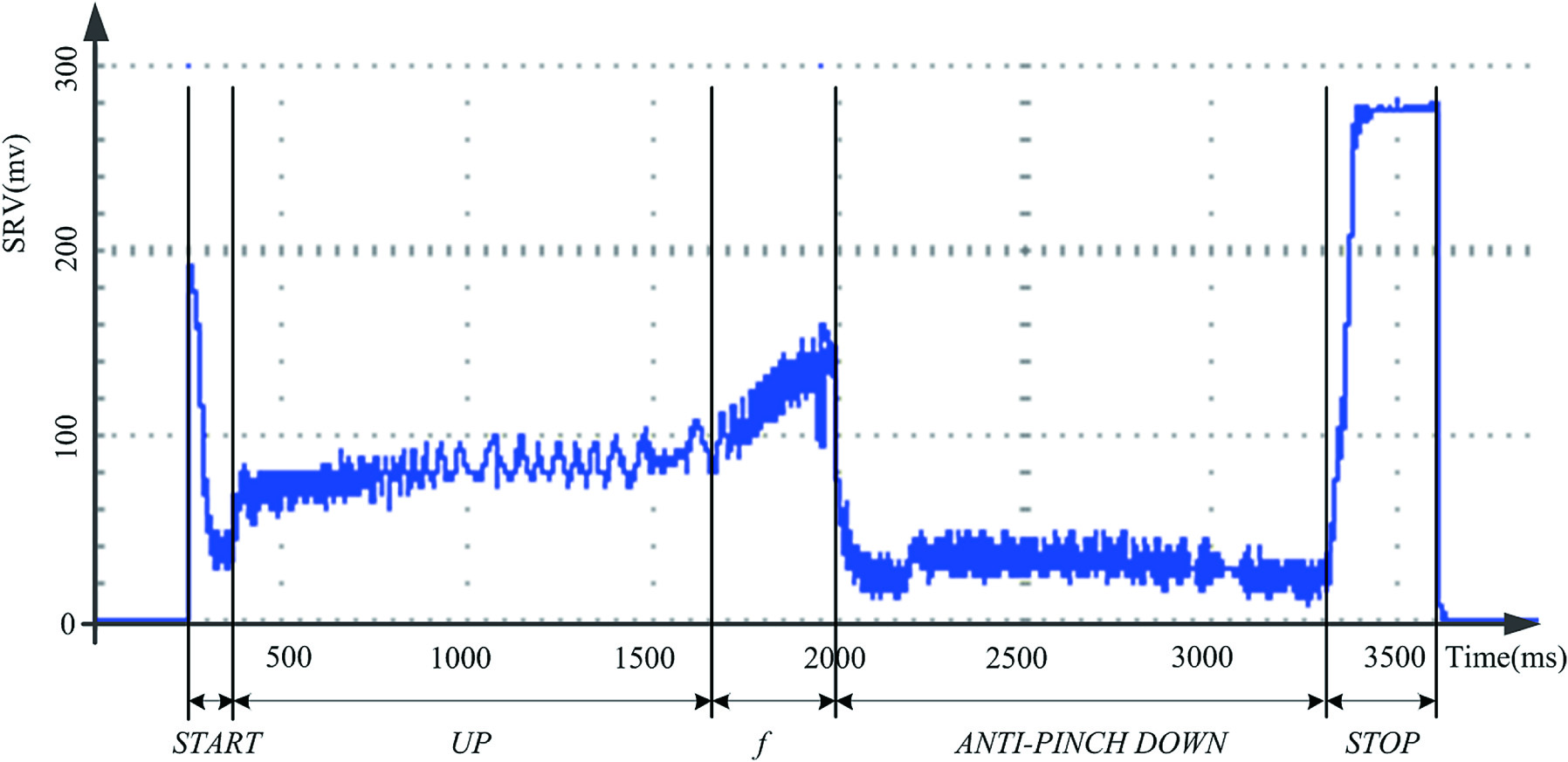 Fig. 11. The change of sampling resistance voltage when the window glass anti-pinch reverses.
Select five points on the car window on average [21], as shown in Fig. 12.
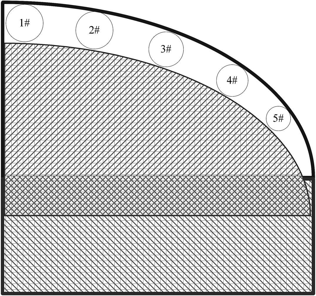 Fig. 12. Schematic diagram of power windows.
When the car window rises, the anti-pinch force of these five points are tested separately, a total of 10 sets of anti-pinch force data are tested, and the corresponding average anti-pinch force is obtained. The results are shown in Table 1, which meet the design requirements.
TABLE I Anti-Pinch Force of Different Window Positions
| Test point | Anti-pinch force /N | Average force /N | |||||
|---|---|---|---|---|---|---|---|
| 1# | 69.2 | 67.6 | 59.8 | 68.4 | 65.7 | 66.3 | |
| 67.2 | 69.3 | 66.7 | 62.9 | 65.8 | |||
| 2# | 75.4 | 70.6 | 71.9 | 70.5 | 73.7 | 72.9 | |
| 70.1 | 72.6 | 74.4 | 73.9 | 75.7 | |||
| 3# | 77.6 | 75.3 | 78.4 | 74.5 | 76.1 | 76.7 | |
| 78.3 | 76.5 | 77.3 | 78.1 | 75.1 | |||
| 4# | 79.3 | 75.8 | 77.9 | 76.7 | 78.5 | 78.0 | |
| 79.5 | 77.8 | 76.9 | 79.7 | 78.5 | |||
| 5# | 78.5 | 80.1 | 79.3 | 77.7 | 79.6 | 79.0 | |
| 80.2 | 79.8 | 78.1 | 79.3 | 77.9 | |||
B.RIPPLE COUNT
The model is established by MATLAB, and the collected motor current data are simulated to verify the feasibility of the phase difference method ripple count.
The simulation result is shown in Fig. 13, where the red curve is the motor current, the black curve is the current ripple, and the blue curve is the counting pulse.
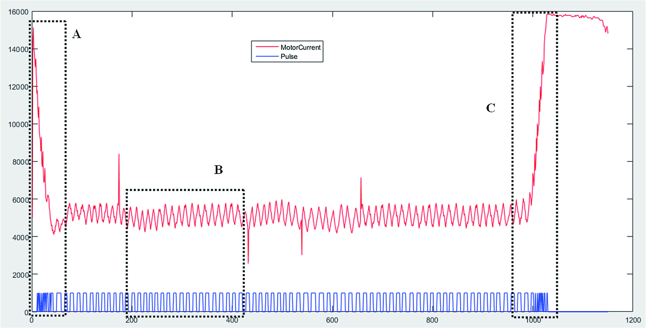 Fig. 13. MATLAB simulation of phase difference method.
In Fig. 13, the red curve is the motor terminal current, and the blue curve is the square wave pulse converted from the ripple pulse. The abrupt current on the motor current curve is a burr. It can be seen from the figure that the phase difference method is used to convert the ripple into a square wave, and large burrs can be filtered out to make the result more accurate. These operations are all through the phase difference method to achieve. Figs. 14–16 are enlarged views of the area A∼B in Fig. 13, respectively.
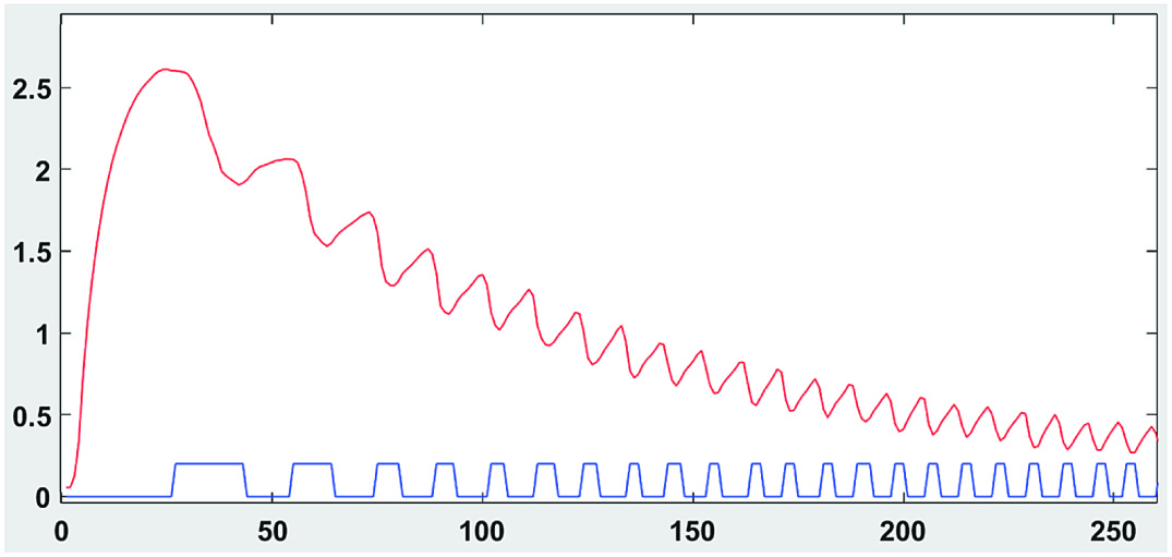 Fig. 14. Enlarged view of area A.
 Fig. 15. Enlarged view of area C.
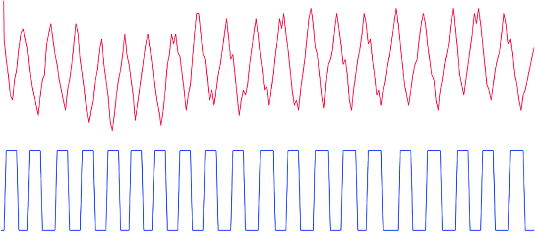 Fig. 16. Enlarged view of area B.
Fig. 14 is an enlarged view of area A in Fig. 13. From this figure, it can be seen that during the motor startup stage, due to the very large change in the motor current, the ripple pulses in the collected current are extremely irregular. Therefore, the square wave pulse obtained from the ripple pulse conversion is also very irregular and varies greatly. Therefore, it may cause the converted square wave number to be more than the actual square wave number, and eventually cause the ripple pulse to count more.
Fig. 15 is an enlarged view of area C in Fig. 13. From this figure, it can be seen that during the motor locked-rotor stage, due to the rapid rise of the motor current, it remains relatively stable after rising to the locked-rotor current. It can be seen from the collected current, the ripple pulse in the current changes very greatly. Therefore, the square wave pulse obtained from the ripple pulse conversion is very irregular, so it may cause the converted square wave number to be more than the actual square wave number, and eventually cause the ripple pulse to count more.
Fig. 16 is an enlarged view of area B in Fig. 13, from which it can be seen that during the normal operation of the motor, the collected motor current is relatively stable, and the ripple pulses in the current are relatively regular. Therefore, the square wave pulse obtained from the ripple pulse conversion is relatively regular, so the process of the ripple to the square wave can be converted normally without causing the ripple pulse to be counted more.
To sum up, when using MATLAB to simulate, during the motor startup and stall phases, the current changes greatly, resulting in a large difference between the count value and the actual value, so the ripple count in these two stages needs to be processed separately. But during the normal operation of the motor, the count value is basically equal to the actual value, and normal ripple counting can be performed.
It can be known from MATLAB simulation that the phase difference method ripple counting is feasible. Therefore, after programming the phase difference method into a software algorithm, the MCU processes the collected motor current data, and the processing results are shown in Figs. 17–19.
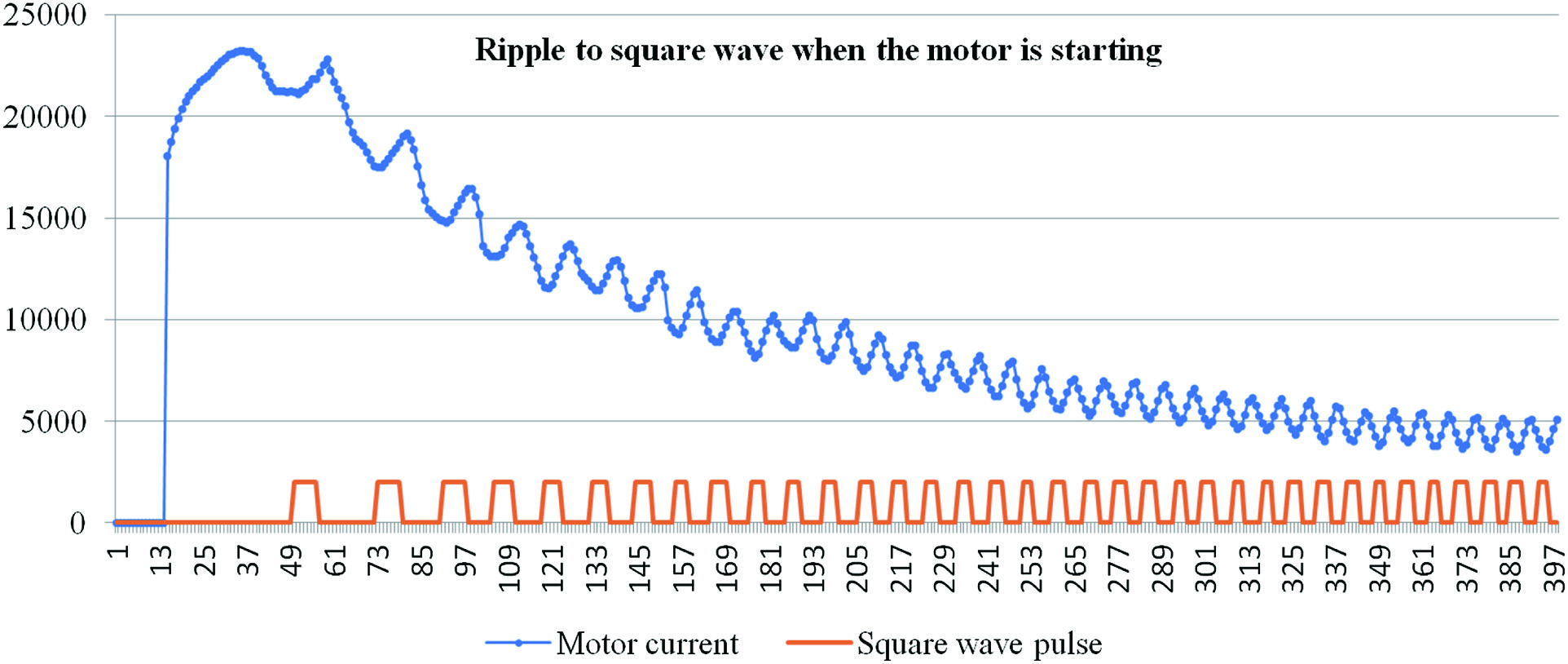 Fig. 17. Ripple count during motor starting.
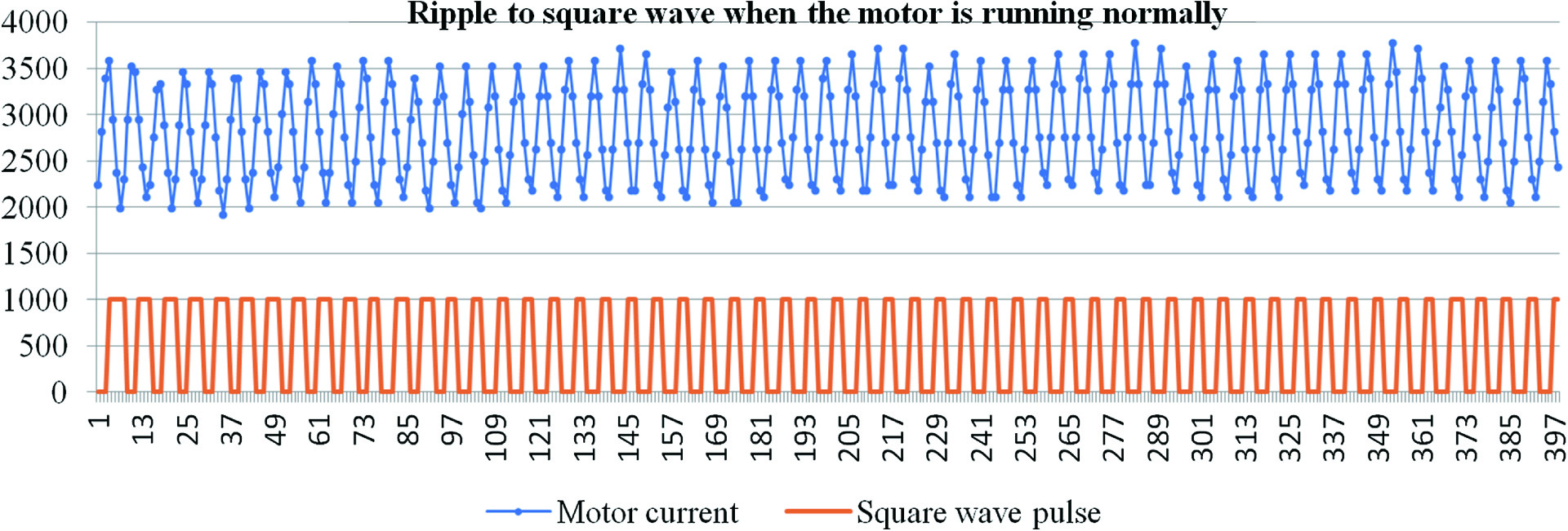 Fig. 18. Ripple count during normal operation of the motor.
 Fig. 19. Ripple count during the motor locked rotor.
Fig. 17 is the graph of the ripple pulse converted into a square wave pulse during the motor startup phase, and the ripple count can be performed through the converted square wave pulse. It can be seen from Fig. 17 that, similar to the MATLAB simulation Fig. 14, in the current collected at the moment of starting the motor, there is no ripple pulse, or the ripple pulse is extremely irregular, making the converted square wave pulse irregular, resulting in the ripple count at the moment the motor starts is too high.
Fig. 18 is a graph of the ripple pulse converted to a square wave pulse during the normal operation of the motor, and the ripple can be counted through the converted square wave pulse. It can be seen from Fig. 18 that, similar to MATLAB simulation Fig. 16, in the current collected during the normal operation of the motor, the ripple pulse is relatively regular, so the converted square wave pulse is also relatively regular. Therefore, when counting the ripple, the calculated ripple number is almost equal to the actual ripple number.
Fig. 19 is a graph showing the conversion of ripple pulses to square wave pulses in the locked rotor phase of the motor, and the square wave pulses obtained by the conversion can be used for ripple counting. It can be seen from Fig. 19 that, similar to the MATLAB simulation Fig. 15, before the motor enters the stall, the situation is the same as during normal operation. After the motor enters the stall, the current gradually rises. Therefore, in the locked-rotor stage, the ripple pulses in the collected current are extremely irregular, or there is no ripple pulse, so that the converted square wave pulses are irregular, resulting in an excessively large ripple count.
C.INTELLIGENT SPEED REGULATION
When the window glass running to the deceleration area, adjust the PWM duty cycle to make the window glass start to decelerate, as shown in Fig. 20, until the minimum duty cycle, the motor stops running.
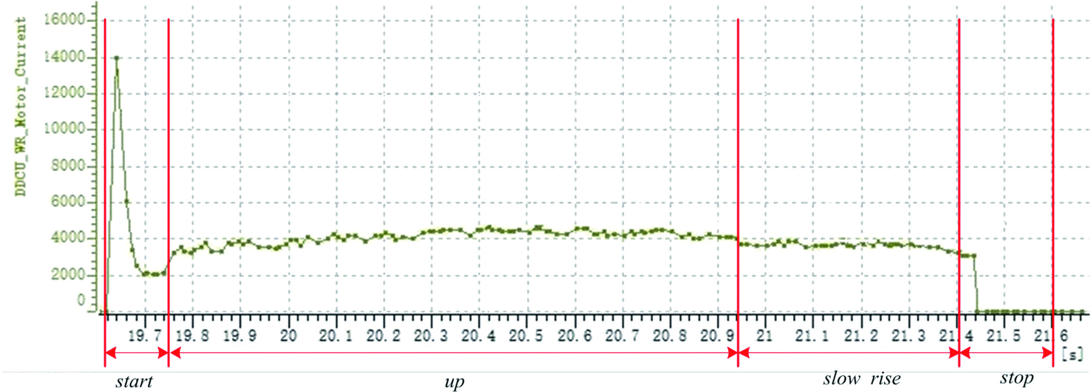 Fig. 20. Intelligent speed regulation.
It can be seen from Fig. 14 that when the car window is rising, when it is about to reach the upper locked-rotor position, after the electric window regulator detects this state, it starts to decelerate and rise until it reaches the upper locked-rotor position, the controller controls the motor to stop moving.
VII.CONCLUSION
This paper designs a set of electric window regulator system based on intelligent control, which realizes functions such as intelligent anti-pinch and intelligent speed regulation.
After the system has completed many complete tests, the anti-pinch success rate is more than 97%, the anti-pinch force varies within the range of 80 ± 12 N, and the average change rate of the calculated value of the window glass position from the actual value is 0.89%. Meet the requirements of GB7258-2017 standard, verify the feasibility of the above algorithm, it is superior to traditional algorithms in control accuracy: Without any sensors, it can prevent the accidental pinch prevention of the window during the ascent, which effectively avoids the accident of pinch injury and improves the safety and reliability of the system.
The system can realize the deceleration and stop of the window glass before reaching the hard stop, and the success rate is more than 99%, which achieves the purpose of protecting the motor and its mechanical structure.