I.INTRODUCTION
The industrialized nations are trying to legislate carbon zero emission by 2050. This pledge can be achieved by changing the energy production from unrenewable to renewable energy such as wind power or have the capabilities to remove carbon particles from the atmosphere through a process called carbon offsetting. The main concern with the overall operation of the wind tower is that it is too expensive to inspect and to maintain. Moreover, it is dangerous or hazardous for people to carry out inspection on the tower [1].
The current method of inspection of the wind tower structure commonly involves the use of scaffolding that allows locating of damages in the tower, generator, and blades. This is not only dangerous for humans but also incurs substantial cost to the company. Therefore, an automated climbing robot would be advantageous for the inspection of the wind tower. The common ways that the robot is used for climbing the wind tower of a structure are the following: adhesion methods with the use of magnets in the wheels that will provide a strong adhesion force to the tower and spring loaded adhesion method [2], [3]. Another method is electroadhesion. Electroadhesion uses electrodes to be able to create an electrostatic force of attraction from the robot to the surface.
The magnetic method is commonly used in inspection tasks. The magnetic adhesion is utilized in the wheels as this provides a strong adhesion force to the surface, and thus avoids any loss of tractive force. The orientation of the magnets that are on the wheels will be about the same distance from the surface, and this will determine the gap between the magnets [4]. This method is fast and very reliable, and it has a strong adhesion force. However, it can only be used on the surface that has a strong magnetic force, and this method is not very efficient as it wastes energy.
The suction adhesion method is employed in various applications like inspecting tall buildings, such as cleaning windows. Thus, in order for the robot to stay on a vertical wall, two adhesion mechanisms, namely, active and passive adhesion will be required. Active adhesion uses the negative pressure or electrostatic to exert strong adhesion force. It allows to control the attachment and detachment for which a mechanism such as a vacuum pump will be required. Passive adhesion mechanism can have a large adhesion force, and it could be used without a power supply, and no need for an actuator to change the attachment and detachment of the robot [5], [6]. However, this method will not be useful on all surfaces especially in surfaces that are bulky or surfaces that are not smooth or clean.
The electroadhesion is another technique in which it uses electrodes to be able to create electrostatic force attraction from the device to the surface; this gives an excellent adhesion in most materials like wood, concrete, and steel [7], [8]. However, the process fails when there is asurface that has moisture and the robot moves only in one direction. On the other hand, electroadhesion can make a device lighter, and it will allow using very low energy.
Dry adhesion method was inspired by geckos or the so-called Van Der Waals force. This technique can generate forces between the surface and the fibril that is usually attached to a climbing robot. It consists of three stages, namely, (1) connecting to the surface, (2) preloading in which there is an increase in the adhesion force, and (3) peeling which removes the adhesive from the surface, so the robot will be able to move. This method is similar to the gecko feet [9], [10]. Some climbing robots do not use much energy for the adhesion, which show a great potential in the industry. However, many studies state that the moisture and the dust on the surface could reduce the adhesion mechanism.
The wheeled method uses magnetic wheels as the adhesion method. However, a different mechanism developed for inspection of cylindrical structures at London South Bank University consists of three modules joined in a triangular structure in which the robot can climb along the pipe, and the wheels can rotate 90°. This can be done by using spring forces to grip around the tower and be able to climb [11], [12].
Legged method is a further type commonly used. A legged robot is designed based on the task it needs to perform. Such a robot has several controllable joints that allow a multi-degree of freedom for its mobility. The robot may include vacuum cups located at each foot of the device. Depending on how many legs the robot has, the legs are separated into two groups. The first pair of legs will be working on attaching the legs to the surface, and the other group will be moving to the desired position and adhere to the surface [13]–[15]. This type of robot has a multi-degree of freedom that is suitable for uneven structures. However, the locomotion consumes a significant amount of energy, and the mobility of the robot is slow as it does not have continuous movement.
The tracked method is mostly used in applications such as inspection and maintenance. A tracked type of robot is relatively faster and less complex to build. Some robots also use the magnetic adhesion method to move the robot. Others have tracked belts with magnets in the belt allowing magnetic adhesion with the surface, but it consumes more energy than the wheeled robots.
For wind turbine inspection, the prototype that will be developed needs to climb the whole wind turbine structure. The average height of a wind turbine support structure is around 150 m depending on the area and the country regulations; it is usually made of steel [16], [17]. The prototype is required to climb the structure and be able to rotate 360° around; this will allow the operator to have a better view of the structure and the blades of the wind turbines. The design of the robot needs to handle the load as this will allow the operator to add any sensor to inspect the structure. Moreover,the robot can be adjustable to add a Cartesian scanning arm in which it will allow the robot to climb to the top of the tower and be able to scan for any damages that could be found in the blades of the turbine [18]–[21].
This presents the development of a climbing robot for wind turbine tower capable of ascending, descending, and rotating 360° around the tower in order to carry out routine health monitoring inspection tasks of towers in wind turbine farms. The rest of this paper is structured as follows: section II presents an analysis of the proposed prototype design of the robot, section III provides spring analysis for the robot to adjust to the tower, section IV presents calculation of design parameters for the robot mobility, section V presents control of the robot in simulation setting, section VI presents stress analysis of the robot, and the paper is concluded in section VII.
II.ANALYSIS OF THE PROTOTYPE DESIGN OF THE ROBOT
The robot needs to be able to go up and down in a considerable speed in order to reduce inspection time and be able to rotate 360°. The structure of the design needs to adapt to the tower of the wind turbine. The structural design of the robot needs to be light and be able to adapt to any environmental conditions of the wind turbine structure.
Fig. 1(a) and (b) shows a 3D design of robot in AutoCAD. As noted the robot has three rings that are fixed to each other, and each ring is distributed at 120° to each other in a circular way.
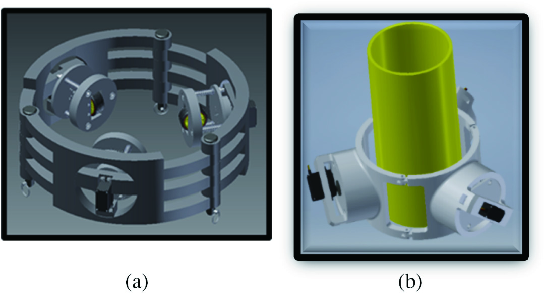 Fig. 1. (a) and (b) Design of the robot in AutoCAD.
As shown in Fig. 2(a) and (b), there are three servo motors, denoted as (1), each attached to the base of the rotational module. The use of springs, denoted as (2), will help the robot to adjust to a tower and will help to overcome any obstacle that can be found in the tower. The parts (3) and (4) are connectedto the microgeared motor which will move the wheel in any direction, like up and down or in a circular motion.
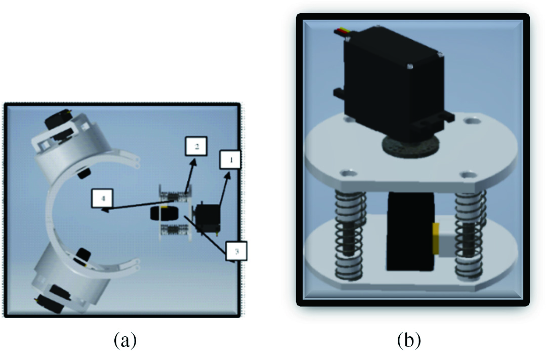 Fig. 2. (a) and (b) View of the rotation module.
The rotational module as shown in Fig. 3(a) will allow the robot to rotate 360° around the tower. The servo motor is mounted in a suspension structure, as the servos are in a central position (0°). This will allow the robot to move up and down the tower. However, when the servos rotate to the desired angle (90°), this will enable the robot to go in a circular motion, which will meet the requirements for this project.
 Fig. 3. (a) and (b) View of the rotation module and a prototype module.
The prototype module of the robot is shown Fig. 3(b). As each module is at 120° from each other, this allows the robot to hold firmly onto any surface. The wheels that are fixed every 120° in the form of an equilateral triangle give the robot stability when it is climbing, as the mass is distributed to the center of the robot, which allows more stability.
III.SPRING ANALYSIS
The spring will help the robot to adjust to a tower to overcome any obstacle that can be found in the tower, so it is necessary to make calculations to find suitable spring for the robot.
The calculation of the spring preload to hold the weight of the assembly robot that is approximately of 1.55 kg and with a safety factor of 2.5 is given as
Adding a safety factor of 2.5 for the mass of the assembly, the resulting is force that needs to be restrained by a lateral force from the spring, denoted as N in Fig. 4(a). Thus, , assuming that is the coefficient of friction and is to take into account that of the weight, to be able to calculate the lateral force for one set of the wheels. Therefore, ; . Therefore, each wheel of the robot needs to exert 70.6 N through the springs, as the springs are parallel, the force is divided equally between them, and each must be preloaded with around 24 N to hold the weight of the device. Fig. 4(b) and (c) shows the wheel position for the translational movement and rotational movement for the robot.
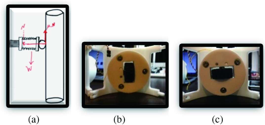 Fig. 4. (a) Forces on the spring. (b) Servo translational movement. (c) Servo rotational movement.
IV.PARAMETER CALCULATIONS FOR CLIMBING ROBOT MOVEMENTS
Parameters needed for the climbing robot design are calculated for three movements—upward, downward, and rotational as shown in Fig. 5. The following specifications are considered in the calculations: weight of the robot as 1.55 kg, pipe diameter as 150 mm, and pipe height as 400 mm. Two geared motors for movement up and down and three motors that will allow the rotation of the robot. Geared motors—shaft is 9 mm long and diameter is 3 mm; torque with no load = 0.49 Nm, N = 100 rpm, and earth gravity = 9.8 m/s2.
 Fig. 5. Force movement direction.
A.UPWARD MOVEMENT
2)ACCELERATION
Using the resultant force, the acceleration of the robot climbing the pipe can be determined as, ; .
B.DOWNWARD MOVEMENT
2)ACCELERATION
Using the resultant force, the acceleration of the robot climbing the pipe can be determined as,
C.ROTATIONAL MOVEMENT
2)ACCELERATION
Using the resultant force, the acceleration of the robot climbing the pipe in rotational movement can be determined as,
3)VELOCITY
For rotational movement velocity upward, first, calculate helical length orbit and determine how long time needs to travel the distance.
Pipe circumference = πD= 3.14 × 0.15 = 4.71 m
Velocity of robot is 0.22 m/s, so the time needed for helical length is,
So the velocity of rotational movement in vertical motion is,
V.SIMULATION OF THE ROBOT CONTROL
The control simulation was realized in Simulink software to monitor the expected output parameters that were required for the robot as shown in Fig. 6.
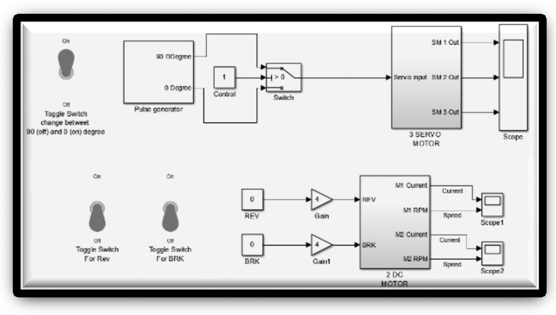 Fig. 6. System to control the robot.
Fig. 7(a) shows the connection of the dc motors. They are both connected to the same supply and control signal. The two dc motors are to behave in a similar way. The dc motor block has four inputs and two outputs. The two inputs supply a rail, while the other two are for reversing the direction of the motor and breaking it. The outputs of the motor are current and the speed of the motor. During forward motion, the speed is positive and when reversing the speed is negative. The dc motor will only reverse or break if the control signal is greater than the threshold voltage of 2.5 V. Fig. 7(b) shows contents of the block diagram of the dc motor. The block diagram of the dc motor comprises a controlled pulse width modulation (PWM) voltage, an H-bridge, current sensor, dc motor, and rotational motion sensor.
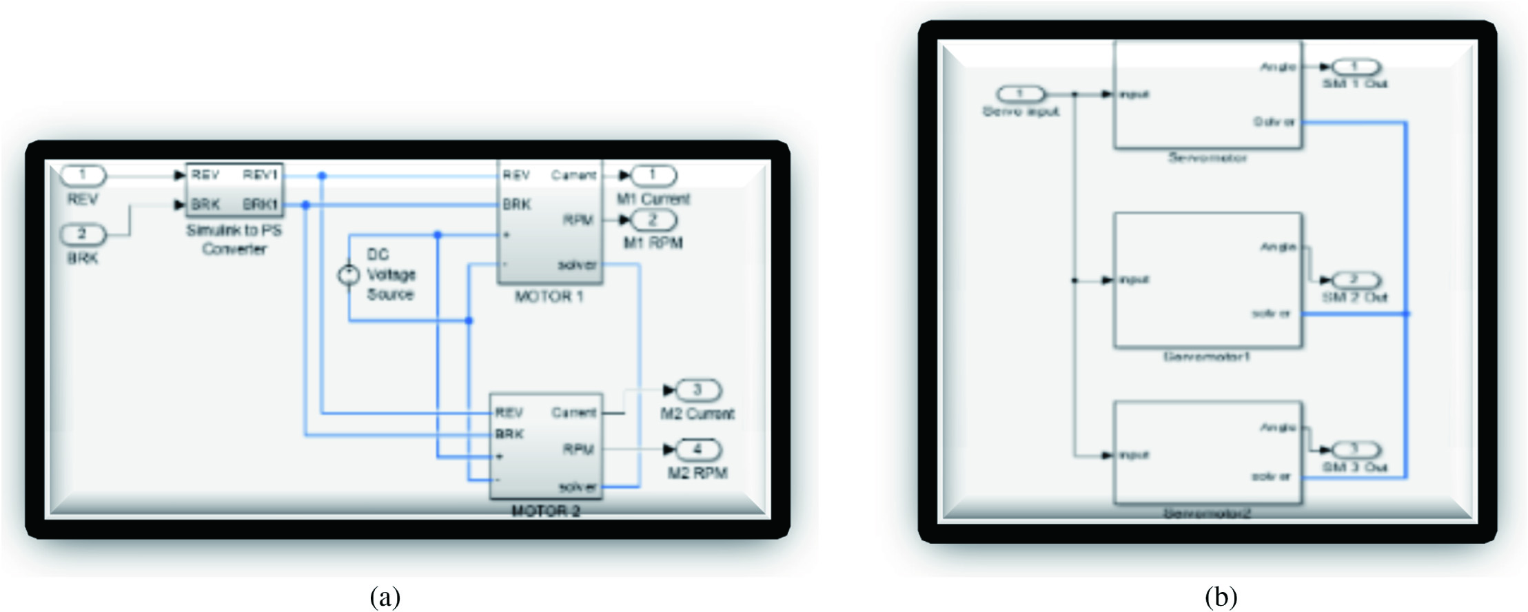 Fig. 7. (a) DC motor connection. (b) Block diagram of the dc motor.
The model of the servo motor is shown in Fig. 8(a). The three servo motors have the same inputs and outputs. Fig. 8(b) shows the model of the servo motor which comprises two parts: electrical and mechanical. The electricalpartis comprised of a pulse to voltage converter which converts the pulse signal to an analog voltage. This voltage then converts the angle using a lookup table. A saturation block is used to ensure that the angle does not exceed 180°, which is the maximum the servo motor can rotate. The angle is then fed into a controlled voltage source for application to the dc motor. The dc motor is connected to a gear of ratio 5.
 Fig. 8. (a) and (b) Simulink model of the servo motor.
Fig. 9(a) and (b) shows the simulation results of torque against current, speed, output power, and power efficiency for the two input voltages of 9 and 18 V. As noted, the torque is proportional to current and inversely proportional to speed. The power efficiency increases up to a certain value of torque and then decreases linearly.
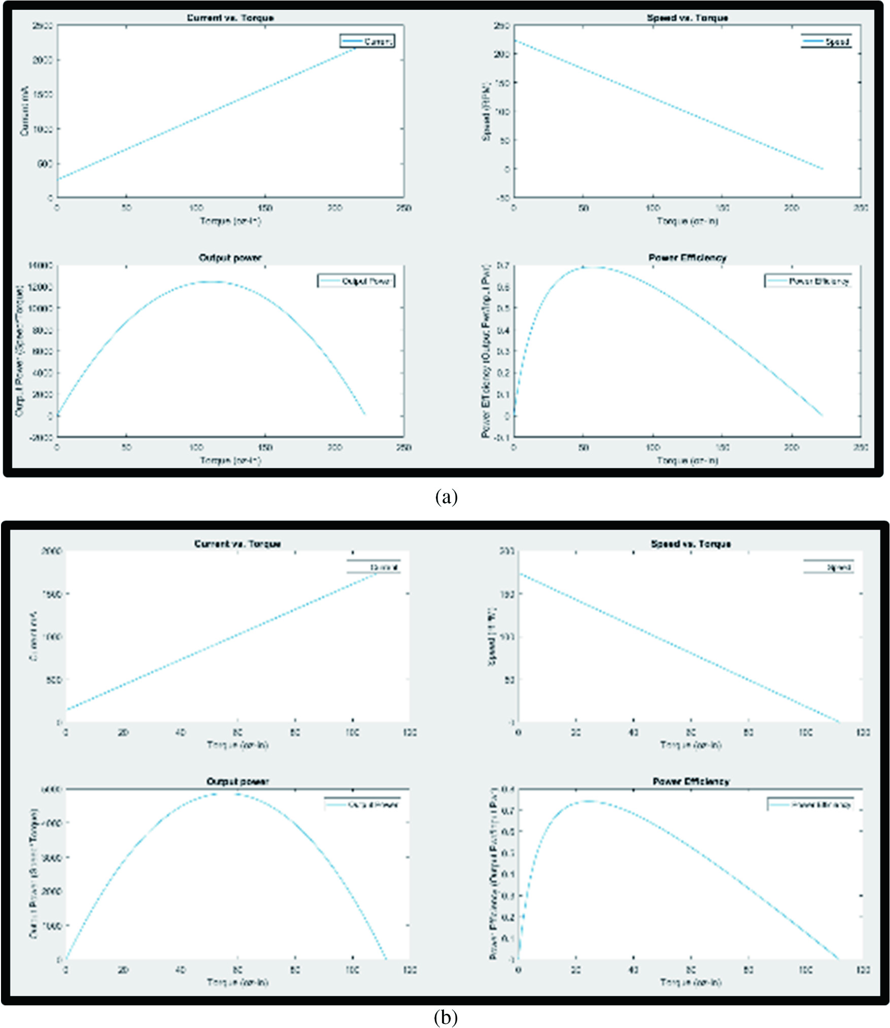 Fig. 9. (a) Simulation Torque analysis results at 9 V. (b) Simulation Torque analysis results at 18 V.
VI.STRESS ANALYSIS
The development of the 3D robot model created in AutoCAD, as shown in Fig. 10, allows analysis of the stress that will be placed on the structure when the robot is moving.
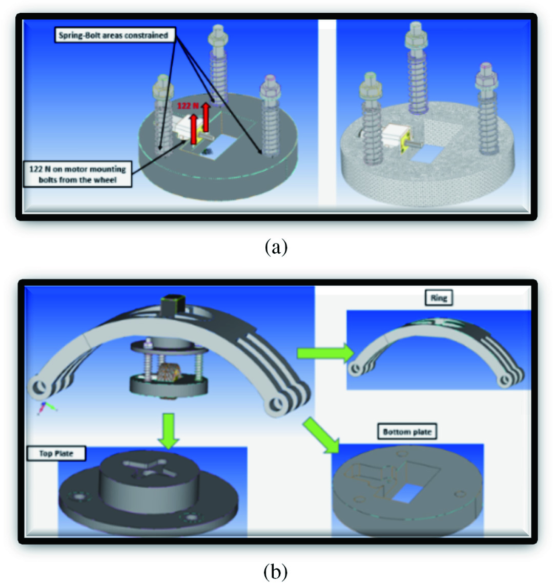 Fig. 10. (a) Robot parts with stress analysis. (b) Force applied.
Fig. 10(b) shows the force that was applied to the bolts of the bracket that fixes the microgear motor to the base, as this part will hold an important function, as it has to support all of the stress and force that will be applied when the robot is moving.
Fig. 11(a) shows that the maximum stress that was applied is around 6.95 MPa. It indicates that the materials used for the prototype will be able to cope with the stress that will be generated, as the acrylonitrile butadiene styrene (ABS) Plastic Yield Stress is around 44 MPa, which means that there will be a significant margin of safety results from the analysis.
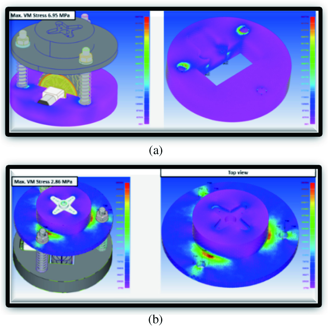 Fig. 11. (a) Stress on the plate holding the servo motor. (b) Stress on the upper plate.
Fig. 11(b) shows the stress that will be available at the base of the servo motor, in which the servo hub will be attached to the base, as this will allow the rotation of the module. The upper plate has a maximum stress of 2.86 MPa at the top of the plate, which has a significant margin of safety as the ABS Plastic Yield Stress is around 44 MPa.
Fig. 12(a) and (b) shows that the maximum displacement in the lower part is 0.041 mm and the upper part is 0.072 mm, and the total force will act on the three springs are 122 N as hown in Fig. 12(c). Fig. 12(d) shows the maximum stress on the side plate holding the servo motor as 3.72 Mpa.
 Fig. 12. (a) and (b) Maximum displacement and stress on the side plate holding the servo motor.
VII.CONCLUSIONS
A spring contact adhesion mechanism wheel driven robot was able to maintain good contact with the tower without sliding. Research into the parameter calculations of coefficient of friction, stress, speed, and acceleration was carried out. Finite element analysis has indicated that the materials used for the prototype was able to cope with the stress generated, and there was a good corelation of safety margin resulting from the analysis.
A prototype laboratory based climbing robot has been developed for wind tower testing in laboratory settings. The prototype robot did not use any specific scale ratio and dimensions that could be used for the real application. The robot was able to climb up and down on the tower and rotate 360° around the tower. A circular ring shape designed robot suited the structure of the wind tower, and was able to move in a stable manner.
An issue noted with the robot was that, the acceleration torque required for the robot to climb was much higher than anticipated, and so higher torque motors were needed. On the other hand, the robot seemed to have no difficulty providing enough adhesive force, and this was developed by the spring mechanism.
There are some improvements that have to be made in order to transform the robot to real industrial use. A differential drive can be implemented by introducing a tracked locomotion to the robot for better maneuverability and traction, and an embedded pressure sensor can be implemented into the electrical system to monitor the payload during real life operation. This is essential as the payload increases greatly due to aerodynamic resistance.
In order to supply the additional power to the robot for the inspection instruments to perform an inspection service, the two batteries can be wired parallel so that the voltage is not doubled, but the total capacity of combined batteries increases. This can be done by introducing an radio control (RC) relay into the circuit to allow part of it to shut down during the climbing up the tower. Once the robot is parked in position, the relay can be used to drop the voltage down to the required voltage for the inspection equipment.