I.INTRODUCTION
Nowadays, with the development of wireless communication such as internet of things (IoT), Bigdata, Intelligent systems, smart cities, machine learning, Wi-Fi, and Bluetooth, all agents of Industrial Revolution 4.0 (IR 4.0) must be capable and compatible with an obliged environment that the system is in. That being said, positioning plays a huge role in determining the position of a user in an environment. Thus, the ability to determine its pose, position, and orientation is key for a successful IoT system. These modernistic technologies are the real deal of infrastructure amenities presenting a more organized and efficient way of living.
The ability of a wireless communication system such as IoT to establish positioning and orientation based on the system it uses and the environment that surrounds the user within a reference point is known as localization. Localization and positioning are two different things, although they are based on the same principle where they refer to a reference point. Localization is a method of navigation from point one to another while at the same time enabling the coordination of the subject based on position and orientation (Pose). Whereas positioning is the ability to identify the coordinates X, Y, and Z of a subject based on the reference point.
In general, to understand the fundamental concept, two main questions should be answered when dealing with positioning: where is the user (start point)? and where is it going (end point)? Based on the first question, it implies localization, and based on the second question, it implies place recognition. Although they seem to be simple questions, answering them is not easy when they involve different wireless communication system and protocol that differ in characteristics and also depend on the environment they are involved in. One wireless communication system may have the ability to be positioned successfully in one environment but may not be successful in another environment, and vice versa. This is due to several factors and parameters that influence the surrounding environment, such as obstacles, pathways, and areas of space, which will affect the system that is being implemented.
In this research, ultra-wideband (UWB) from Pozyx [1–3] is chosen as the wireless communication system to be applied. UWB is a type of radio wave application that operates in close proximity offering different options for channels and low bandwidths, hence a more secure alternative to NFC [4]. The problem that UWB is trying to solve is related to ranging and location accuracy and precision, which is a very common occurrence when dealing with an indoor environment as modern navigation technologies such as mobile mapping are driven by global navigation satellite system (GNSS), that is, Global Positioning System (GPS), Galileo, BeiDou, etc.
The rest of the paper is organized as follows. Section II presents recent studies and previous work. The methodology of this research is presented in Section III. Section IV discusses the results and analysis. Conclusions are drawn in Section V.
II.LITERATURE REVIEW
In recent years, there has been a growing interest in localization and positioning technologies. Researchers and practitioners have proposed various technologies, such as using UWB [5,6], augmented reality (AR) [7,8], and wireless IoT through cross-platform development engine [9,10], to address the challenges of indoor localization. This paper reviews the most recent popular localization technologies, as well as localization within UWB technology, which address the challenges of indoor localization and navigation.
UWB is a technology that offers high-precision distance measurements between UWB transceivers [11–14], which makes it suitable for indoor localization and positioning applications. Nevertheless, UWB has limitations in terms of visual rendering in a real-world environment, which necessitates the integration of other sensor technologies. One of the most widely used sensor technologies is inertial measurement unit (IMU) [15], which can estimate the user’s position based on movement and orientation data collected from mobile devices. The combination of UWB and IMU can enhance the accuracy and robustness of positioning systems.
Cossette et al. [15] demonstrate the extraction of IMU information using a single UWB transceiver, gyroscope sensor, accelerometer, and magnetometer. This information is then used to generate an algorithm for determining the three-dimensional (3D) position of two mobile robots relative to each other. The results obtained indicate an accuracy range of approximately 1 m. Future work should consider testing the algorithm on a mobile robot in a real-world environment with known magnetic disturbances to assess its performance under these conditions.
Choi et al. [7] developed a virtual-UWB-based method that uses virtual anchors (VAs) to localize sensor tags in challenging indoor environments. The system comprises a location estimator and sensor nodes. The location estimator assigns VAs to each sensor node based on the received signals. When at least four VAs are assigned, the angle and the general coordinates can be obtained by applying multilateration methods, which are commonly used in indoor positioning. The sensor node can then provide sensing data for further analysis.
However, the authors argue that the current methods have limitations, especially when they need to be combined for enhanced quality services in challenging indoor conditions. For instance, anchor management can be complicated in 3D space, as the variation in the z-axis movement is much lower than in the x-axis and y-axis. Therefore, these studies should further investigate the possibility of integrating AR and UWB with IMU for real-time indoor localization.
Nur et al. [16] have built a 3D visualization design for a real-time position tracker based on a UWB device. The research intended to build a 3D map application named Peta 3D being able to facilitate and monitor the whereabouts and status of assets in a company. UWB components track every asset movement by placing anchors in every corner of the building and installing them on the assets, and information on the tracker movement data will be visualized in real-time 3D. The realization of this application is accomplished by Autodesk Maya as the design platform integrated with Unity 3D as the engine platform. However, currently, the application is not mobile and does not support different platform.
In 2020, Mimoune et al. [17] evaluated and proposed improved localization algorithms based on the UWB Pozyx system. The paper proposed improved localization accuracy and performance of the Pozyx system using a multilateration algorithm combined with strategically choosing the number of anchors, hence selecting three anchors instead of four. Localization accuracy was achieved at 10 cm accuracy in a line-of-sight (LOS) environment by controlling the number of anchors. The biggest challenge is choosing the finest triplets to achieve good localization performance. Nonetheless, millimeter accuracy can be achieved if four anchors are used instead of three, since four anchors are tailored toward a 3D environment and three anchors are more toward a 2D environment setting. Future improvements in the algorithm of the third anchor are said to be done by using the distance information of the fourth anchor which will lead to 40% better mean error results compared to the Pozyx algorithm. In a non-line-of-sight (NLOS) environment containing multiple paths due to obstacles, accuracy is not obtainable and errors in positioning reach several meters.
In 2019, as stated by Barral et al. [18] accuracy is significantly degraded under NLOS propagation conditions. Therefore, the author focused their research on NLOS classification based on received signal strength (RSS) and ranging statistics obtained from low-cost UWB devices. NLOS environment conditions are significantly important to diagnose first to alleviate error inaccuracies. Machine learning techniques were analyzed to test the viability when implemented in LOS and NLOS conditions using low-cost UWB devices. The result shows that joint classification between LOS and NLOS is feasibly successful taking into consideration the mean of RSS and range. Unfortunately, only the RSS and the range have been considered, since they are the only parameters available from low-cost UWB hardware. The deficiency of RSS is that it is the combination of all power that is reflected and not only forms the desired LOS from the UWB itself.
Similarly, Dabove et al. [19] discuss that the usage of UWB in indoor positioning environments ventures two-way time of flight (ToF) to quantify range measurements and the multilateration method to evaluate the position of Pozyx tags. Based on the test conducted, an accuracy result obtained for a normal 3D environment is average in the range 100 ± 25 mm. Whereas, for a 3D harsh environment, where the test was conducted in a narrow corridor, the average accuracy resulted in around 87.4 mm with a ranging error of ±225 mm. In future testing, several configurations will be considered such as number as an anchor used as a reference point to enable more accuracy and robustness of the test. Be that as it may, these enterprise systems require vast network installation in order to acquire robust, accurate positioning which results in limitations in terms of cost, time, and infrastructure requirements.
Among the most favorable localization technologies other than UWB, wireless networks such as Wi-Fi [20–23], ZigBee [24], Bluetooth low energy (BLE) [25,26] and Message Queuing Telemetry Transport (MQTT) [15] are currently being used as they are easily accessible in most environments and are common in any modern hardware. These methods rely on RSS values from nearby Wi-Fi, ZigBee, and BLE that are measured by the mobile device at a specific location estimator, which then, through several steps, sends information to the second location estimator to determine the final location. A study conducted by Gharghan et al. [24] implements two methods of log-normal shadowing model (LNSM) and neural fuzzy inference system (ANFIS) for indoor and outdoor velodromes. These methods are based on the ZigBee’s RSS indicator anchor nodes. The results showed that, compared to the approximate estimate by the LNSM approach, the distance estimation accuracy was increased by 84% and 99% for indoor and outdoor velodromes after applying the ANFIS optimization.
Similarly, Al-Bawri et al. [27] address the issue of indoor localization through the RSS of Wi-Fi at a 2.4 GHz frequency. The system only uses fixed base stations with simple non-reconfigurable antennas. Through several conditions, such as direct LOS and first order, wall reflection is used to estimate signal strength, which offers simplicity with the wireless communication system.
MQTT is a publish-and-subscribe protocol that provides efficient and secure data communication among devices [28]. MQTT can facilitate indoor navigation by enabling devices to share information such as sensor data, user information, and location estimates [29–32]. Jiang et al. [33] adopt three major frameworks in their indoor location-based augmented reality framework (ILARF), which implements AR visualization, indoor localization unit (ILU), and context-aware message exchange through the utilization of MQTT protocol containing servers for clients to subscribe and publish IMU data. The localization system is intended for an indoor gym application known as Gym Augmented Reality (GAR), where users can interact virtually and at the same time know each other’s whereabouts within the application.
As the GAR app is still in prototype phase, it has some limitations, such as being implemented in a room instead of a real gym environment and having incomplete functions from the ILARF system. The authors suggested future work will enhance the functionality, interaction, and information of GAR, such as adding path planning and 3D views of exercise moves.
Although these wireless technologies offer easy accessibility and are more extensive, in most cases, the RSS will composite the strength of all reflections rather than just the power of the desired LOS, which makes it very challenging to connect the RSS value to the actual distance. It is also susceptible to interference from other devices and requires a significant amount of infrastructure to be set up [25].
In summary, the methods that have been applied in previous works do not fully exploit the UWB technology’s own parameter in relation to other technologies. Therefore, the position accuracy obtained varies from meters to centimeters.
This study aims to achieve millimeter accuracy in positioning using Pozyx UWB. This is done by utilizing the onboard parameters in the Pozyx UWB device itself, without requiring an additional wireless network system or an external bulky sensor. The significance of this research lies in obtaining a precise position, while the subject receives real-time visual information and detailed IMU data. The system proposed integrates UWB technology Unity 3D cross-platform development engine through IoT to access onboard IMU data from the tags and anchors in order to achieve high accuracy and robust indoor positioning. This study also contributes to developing accurate and cost-effective indoor positioning and navigation systems.
III.METHODOLOGY
A.SYSTEM ARCHITECTURE
This research paper focuses on using UWB radio wave technology from the Pozyx device. It uses multilateration for a 3D indoor environment with the UWB_ONLY algorithm as a standard positioning algorithm provided by Pozyx. Two-way ranging (TWR) wireless network is the protocol for positioning techniques in which the wireless network protocol measures ToF UWB radio waves between the initiator master tag and the responder anchors. Figure 1 shows the overview flow chart for Pozyx UWB.
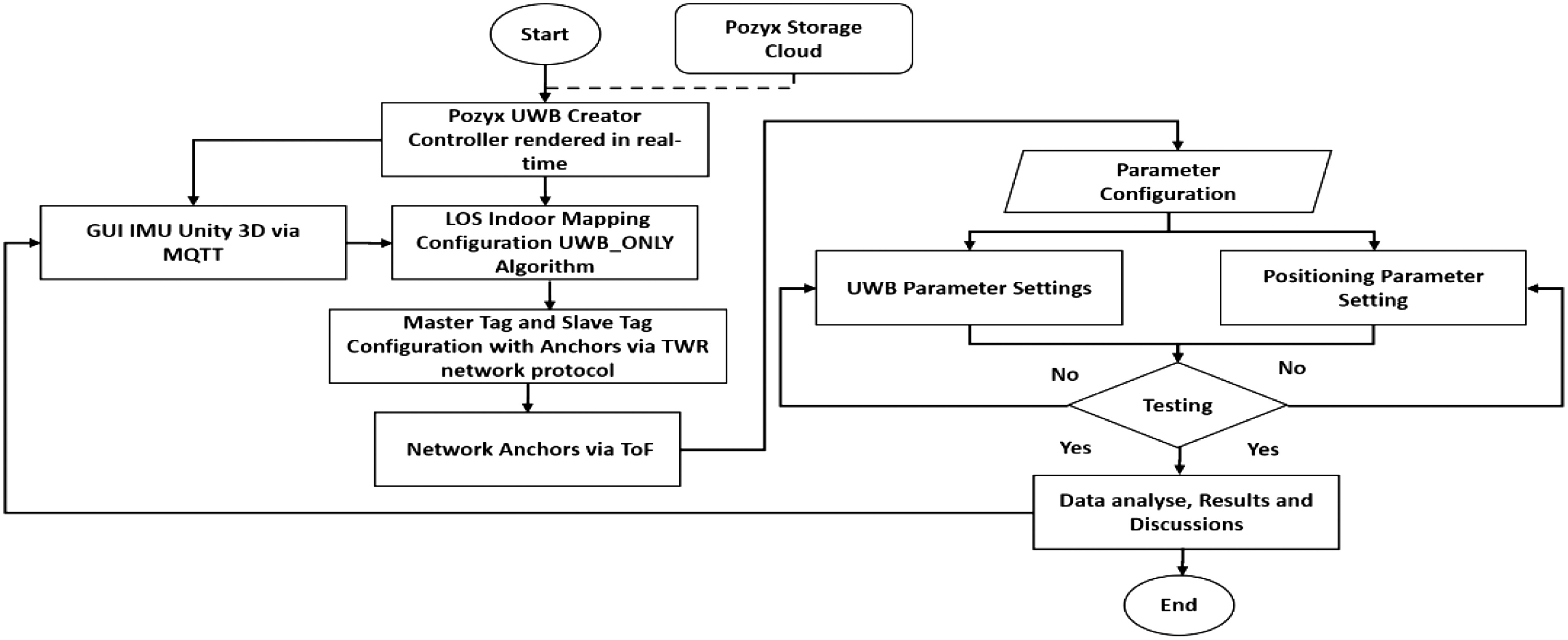 Fig. 1. Pozyx UWB overview flow chart.
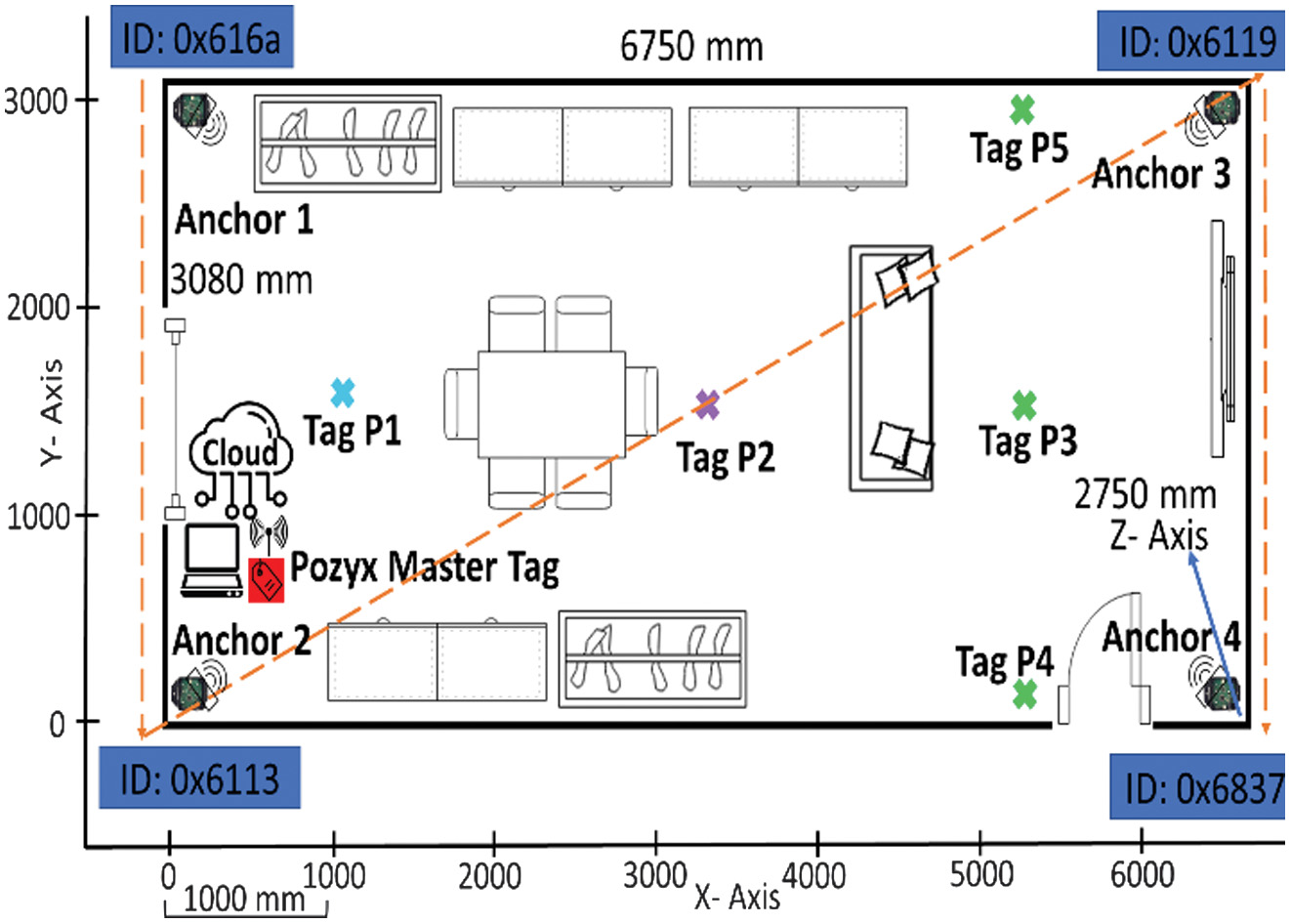
In this paper, the accuracy and range of UWB radio waves for Pozyx were tested in an indoor LOS environment as shown in Fig. 2. The NLOS environment was not taken into consideration as previous works have proven that although UWB is capable of obtaining positions in NLOS, due to obstacles and occlusions such as brick walls and metal barriers, it will greatly contribute to position accuracy, and measurement errors obtained will vary widely.
The constant parameter for the environment was set to four anchors and two tags (master tag and slave tag). Each floor plan was first tested with the default parameter set by Pozyx for positioning setting and UWB setting. Changes in setting parameters were made and are compared with the conventional method which is discussed in the result and discussion.
Real-time rendering of the indoor floor plan goes through the Pozyx Creator Controller where UWB lines are visible and real-time locations of the master tag, slave tag, and anchors are accessible. For the purpose of this research, the master tag known as the server tag was connected to the main server laptop and rendered in a red color icon in the Pozyx Creator Controller.
The slave tags were renamed as person tags P1, P2, P3, P4, and P5 as indicated in Fig. 2 enabling location tracking and range accuracy of a person.
The anchors are positioned in accordance with the lowest ID, first at the top right corner of the floor plan, which also acts as the origin position, and later followed by other anchors’ ID in ascending order shaped like an inverted “N” alphabet. The configuration was to allow the ease of tracking of UWB range later in the research.
B.LOS DEFAULT SETTING
Default positioning settings were first set and tested as shown in Table I. The default setting was first chosen as it was set by the manufacturer as a standard guide. As stated by the manufacturer datasheet [4], the default setting parameter would suffice for other setups, but not every installation is the same to achieve the best results, parameter setting adjustments are required.
Table I. LOS default positioning setting
| Positioning parameters | Default positioning setting |
|---|---|
Off-board | Set to off |
Algorithm | UWB only |
Dimension | 3D |
Height | 0 |
Ranging protocol | Fast |
Filter type | Moving average |
Filter strength | 5 |
Sensor data | Coordinates and orientation |
UWB setting parameters were set up in Table II. The fast-ranging protocol was used on UWB channel 5, with a preamble length of 1024, a PRF of 64 MHz, and a bit rate of 110 kbps. Tests were conducted within a floor area ranging from 6750 mm to 3080 mm. In total, 50 range measurements were collected and 10 measurements for each point were taken to distinguish the accuracy and range correlating to Pozyx’s claim for LOS indoor environment considering several little obstacles in the environment.
Table II. LOS default UWB setting
| UWB parameters | Default UWB setting |
|---|---|
Channel | 5 |
Data bit rate | 110 kbits/s |
Pulse repetition frequency (PRF) | 64 MHz |
Preamble length | 1024 |
Tx gain | 11.5 dB |
C.LOS FINE-TUNE SETTING
With the intention of getting the optimum outcome of the technology, fine-tuning was done in the positioning settings. Fine-tune is based on UWB radio wave that suited the criteria and condition of the environment floor plan, that is , obstacles, barriers, moving objects, and metal density in the environment itself. Based on the criteria and conditions recorded, we concluded to fine-tune the parameter as shown in Tables III and IV. The result of whether the fine-tune setting affected the accuracy, range, and rendering in the Creator Controller is further discussed in Section IV.
Table III. LOS fine-tune positioning setting
| Positioning parameters | Default positioning setting |
|---|---|
Off-board | Set to off |
Algorithm | UWB only |
Dimension | 3D |
Height | 0 |
Ranging protocol | Precision |
Filter type | Average |
Filter Strength | 5 |
Sensor data | Coordinates only |
Table IV. LOS fine-tune UWB setting
| UWB parameters | Default UWB setting |
|---|---|
Channel | 2 |
Data bit rate | 6.81 kbits/s |
Pulse repetition frequency (PRF) | 64 MHz |
Preamble length | 512 |
Tx gain | 15.5 dB |
D.RANGE AND ACCURACY ERROR
To compare the accuracy of true distance versus measured distance, each actual coordinate of the X-axis and Y-axis for P1, P2, P3, P4, and P5 is first defined using Pozyx UWB. Based on the coordinates, true distance and measured distance can be obtained using Equations (1) and (2):
where dt, Xt, and Yt are the true distance and coordinates of X-axis and Y-axis. Whereas dm, Xm, and Ym are the measured distance and measured coordinates. With the distance obtained, using the Pozyx UWB static measurements were taken to acquire 10 positions for each point P1, P2, P3, P4, and P5. This was to distinguish which parameter setting best suited the floor plan and interpret which had the least accuracy error. Using Equation (3), accuracy is best represented using relative error: In the interest of comparing different parameter settings to procure the best UWB accuracy, relative error, er, is defined as a value that should not be more or less than ±0.5% estimated to be within 100 mm claimed accuracy.E.MQTT CONNECTION
MQ Telemetry Transport, or MQTT, is known as an IoT protocol. It is used as a medium of communication between the Pozyx Creator Controller and Unity cross-platform development engine to extrude tag and anchor sensory IMU data such as coordinates, orientation, and acceleration.
This is done by using the publish or subscribe method. M2Mqtt library was used for MQTT functionality in Unity 3D. Using the JSON.Net Unity asset, MQTT tag data is transferred as a JSON array. The tag’s data come in as an array of individual tag packets. By subscribing, users will be able to get the newest position of tag as soon as they are available. C# code is used to keep track of the tag’s ID that is respawned when a new position is available when connected via the Pozyx Creator Controller.
IV.RESULTS AND DISCUSSION
The research has been carried out in an indoor room containing several pieces of furniture located inside as obstacles. To portray a 3D hyperboloid multilateration positioning system, four anchors are placed in every corner of the room allowing accurate tag position. The anchors acted as reference points for the tags to localize which initially estimated the position of the tag. Radio waves are transmitted to the tags by anchors using the ToF technique. In this research, enabling master tag connection through a laptop permits the prescription of packets from the server tag to the anchor calculating each distance in between a roundtrip, in other terms known as TWR.
In this case, comparing the range for each point P1, P2, P3, P4, and P5 was carried out first with the default setting parameter to analyze the outcome. For the initial setup, the default parameter was set for both the UWB setting and positioning setting. Channel 5 setting was chosen because it is accepted in most countries without any limitation [2].
Real-time rendering of the tags for P1, P2, P3, P4, and P5 for the default setting at first required several trials to obtain a fast constant update rate and the accurate position marked at point “X”; hence, 10 coordinate measurements were taken for each point. Next, the research was repeated using the same procedure but with a change in the parameter setting. All points were set to fine-tune settings as shown in Tables III and IV. While rendering through the Creator Controller, it shows more accurate positioning toward points marked “X.” To prove the theory that the fine-tune setting has more range and accuracy compared to the default setting, line graphs were plotted consisting of true position, default setting parameter, and fine-tune parameter [2].
The measurement index for Figs. 3–5 justifies the default measured position which is indicated in a blue color line. Whereas, for the green color, the line indicates the true measured position, and the orange color line indicates a fine-tuned measured position. The figures, respectively, show the result for LOS indoor floor plan sized 3080 mm × 6750 mm consisting of a constant variable of four anchors and three tag setups. Considering the LOS floor plan was not that big, and the true position was obtained by using a conventional laser range finder.
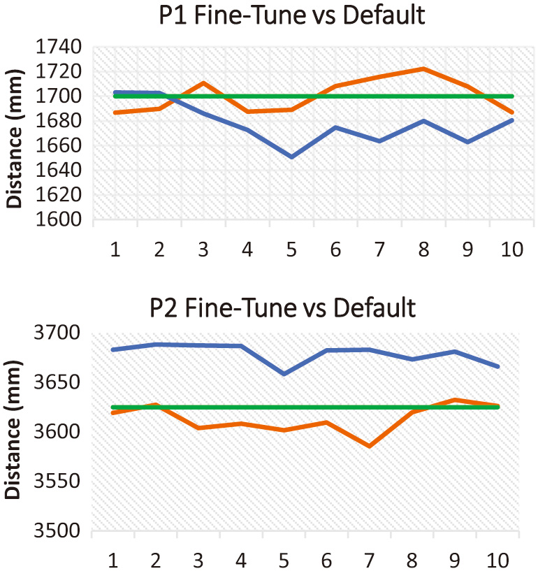 Fig. 3. P1 and P2 fine-tune setting vs default setting.
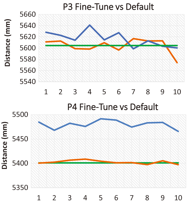 Fig. 4. P3 and P4 fine-tune setting vs default setting.
 Fig. 5. P5 fine-tune setting vs default setting.
For every point, 10 measurements were taken to find the nearest position to the true position. For P1, the true position was 1700 mm, P2’s true position was 3625 mm, P3’s true position recorded was 5604 mm, P4’s true position was 5401 mm, and P5’s true position was 6129 mm. Using X-axis and Y-axis coordinates obtained in the Creator Controller, the measured distance is obtained by using Equation (2). As seen in all five figures, the line graphs plotted, fine-tune settings are more accurate that the orange line representing the fine-tune setting tends to approach the actual true distance (green line) for each point.
This statement can further be proven by comparing the relative error between fine-tune setting and a standard default setting that has been done to all five points. Using Equation (3), the relative errors show behavior for fine-tune settings that have errors value nearest to zero which are −0.03%, 0.003%, 0.32%, −0.03%, and 0.87%, making them much more accurate compared to the default settings which are 1.32%, −1.49%, −0.21%, −1.46%, and −1.21%, hence most ideal setting to be implemented for the LOS indoor floor plan. The positioning error reasoning is supported by the studies that have been done previously by Mimoune et al., 2019 [17].
In terms of accuracy, it can be seen that for all points that are fine-tuned, measured distance accuracy is between 1.55 mm and 115 mm. Whereas, in terms of range, based on the room size of the LOS indoor floor plan, four anchors are sufficient to cover the distances between 4000 mm and 8000 mm.
Comparative analysis of our proposed method is done with existing model done by Mimoune et al., 2019 [17] that shows that our proposed method of using four anchors is able to achieve more accurate measurement compared to using three anchors which obtain an average accuracy of only 860 mm.
To obtain accurate positioning, fast communication between radio waves and constant speed of update rate plays an important role. Based on Table IV, selecting channel 2 as the fine-tuned UWB setting enables lower channel center frequency which then produces a better range in communication. Other than that, when we talk about fast communication, a high data bit rate of 6.81 Mbit/sec is preferred as it permits a shorter message transmission time. Fast communication is must for the preamble length setting. A short preamble length of 512 is chosen as it provides shorter messages and faster communication. Selecting the appropriate setting to enable fast communication is vital for fast update rate and avoiding slow jittery movement in rendering the tags in Creator Controller. Slow jittery movement significantly affects the accuracy. This theoretical reasoning is supported by the studies that have been done by Pereira, 2019 [34].
The difficulty of this research lies in the fact that there will always be some noise in the measurements and because of this some measurements are not accurate, due to that, to circumvent this issue, 10 measurements were proposed to get the best average measurements for each point. In conditions and scenarios where there are lots of noise and bad geometry, the duration time of obtaining measurements is higher; in consequence of this, it is recommended to propagate anchors to cover all directions and not in one straight line, hence reducing positioning errors and decreasing duration time. As a result, the error spreads are very small and range measurements are amplified.
Another finding is that, when fine-tune setting is made, even the smallest or minor movement of the tag will result in millimeters precise measurement reading of the position which results can be seen in P4 and P5. Moreover, the updated measurement obtained for each update rate does not vary that much and has no spike readings but rather results in smooth readings.
As observed, the first three points P1, P2, and P3 are placed in the center nearest to the furniture (obstacles), whereas P4 and P5 are placed near to door and brick wall. The purpose of placing tags in the center near to the furniture and near to the walls is to see the response and reaction of UWB waves when placed near obstacles (furniture as the obstacles) and brick wall, although there is still LOS.
In certain cases where furniture or obstacles are set differently, the accuracy result obtained might differ as occlusion from obstacles play a big role in the LOS of UWB wave between a transmitter and receiver. But the accuracy result might not show a significant loss as UWB technology is able to penetrate most objects that are made from material that conducts electromagnetic wave which as we know UWB is made out.
Based on our analysis and test results, the ability of UWB to penetrate most objects shows that the implementation of UWB can improve the performance of positioning and localization comparing to other state-of-the-art methods as such done by Choi et al. [7]. By using VAs [7], they face problem of obtaining better quality results in harsh indoor 3D space. This is due to the fact that the angular diversity of Z-axis is much less compared to other axis, hence effecting the positioning accuracy when dealt in harsh indoor environment.
Moreover, to solve the LOS issue between anchors and tags, it is recommended to add more anchors in the environment; concurrently, adjustment in UWB parameter settings is recommended. Performing this process should impact the connectivity, range, and update rate between devices. As a rule of thumb, after any adjustments are made on any parameter setting, a waiting period between 5 and 10 minutes is needed to allow the update rate to shimmer down and stabilize.
V.CONCLUSION
In this paper, we considered setting the best parameter for Pozyx’s UWB technology obtained the most accuracy and the least errors for LOS environments. This research also comprised of real-time 2D Pozyx Creator Controller integrated with Unity 3D through MQTT for user graphical user interface (GUI) purposes intended for future work applications. Companion software or better known as Creator Controller is an IoT software connected to the cloud and is capable of delivering wireless onboard sensory information either tag or anchor. It was used to render real-time position and localization of users in the floor plan enhancing UWB POZYX technology for third-person user experience through MQTT.
Wireless communication was feasibly cooperated with Unity 3D as a first-person GUI to share sensory information. Whereas, the Creator Controller for this research acted as the main server for third-person observation in an indoor environment.
Based on the entire process of this research, we concluded several points, including:
- 1.Fine-tune setting for both UWB setting and positioning setting is most preferable in LOS indoor floor plan to obtain an accurate position within 0.15 mm to 115 mm. However, the setting configuration might differ if the environment changed. Thus, it is recommended to recalibrate the position of the anchors and tags being placed in the new environment.
- 2.Fine-tune relative error percentage obtain is nearest to zero value for all five points P1, P2, P3, P4, and P5. Whereas, the default setting had the highest error value of 1.32%.
- 3.The Unity 3D application inference was applicable to be developed as an application in android package kit format for android users.
- 4.What made UWB unique compared to other wireless technologies was that it was a superior technology in terms of bringing the ability or spatial context to IoT devices offering very accurate, very fast, and very secure radio waves.
Some suggestions that we can summarize based on implementation and testing are to develop software applications in other platforms in the future, such as iOS, to enable easier access to other mobile phone users. Other than that, for future work, some physical parameters such as the number of anchors and tags are variables to be considered to increase or decrease in usage and how it affects the accuracy, range, and positioning duration.